6
02/02/10
I've stripped down all the chassis again in preparation for painting and have been busy filling in 'spare' holes and generally tidying things up. The running board brackets are now secured to the frames with 2 screws instead of just one at the bottom and I've fitted a bit of brass angle to the top of the outside motion brackets to take another fixing screw for the running boards which were unsupported in the middle. I've also fastened a piece of angle under the front of the running boards to secure the front curved sections a bit better. Originally, they weren't fastened to the top running boards at all and were just held with one screw into the front buffer beam angle.
Whilst waiting for some filler on the frames to dry, I had a look at the steam turret and the two valves that screw into it. The turret is built up from a bit of copper bar and some bronze (I think) and the two valves screw into this. The original threads were only 3/16" diameter and one valve had actually snapped off when I tried to unscrew it. The other valve was only 'hanging on' by about one thread and could have easily come out under steam. The bodies appear to be brass which is probably why one snapped off.
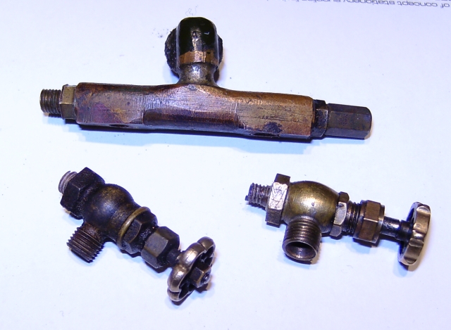
Before 'restoration'
They are very nice little valves and I wanted to retain them so I drilled out the threads in the turret and retapped them 7/32"x40. The valve bodies were then put in the lathe and the original threaded stubs cut off. The bodies were then drilled out to a depth of 1/8" to take a new stub made from phosphor bronze which was then silver soldered in and threaded 7/32"x40 to match the turret.
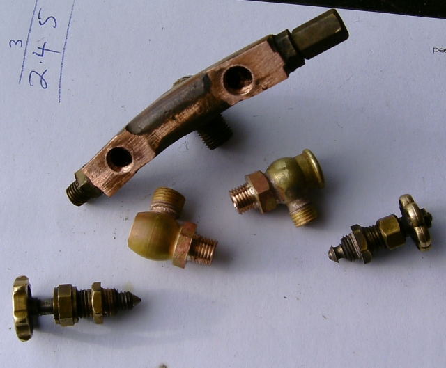
After retapping turret and modifying valve bodies
The turret doesn't have a whistle valve although there was a very small whistle mounted under the righthand running board. It has obviously been removed at some time and may have fitted on the end of the turret that has been blanked off. The other connection on the turret is for the pressure gauge.
Another 'quickie' job was to remove the remains of one of the regulator boss screws that had snapped off in the boiler backhead bush when I removed the regulator from the boiler. I'm not sure if the screws are stainless or plated mild steel, the one that snapped looks like mild steel to me. Fortunately, I managed to drill it out and retap the thread without too much trouble.
27/04/10
A long time since the last update but I have been working on the King when time permits. At the moment it's time for the garden and there's an awful lot to do in there!
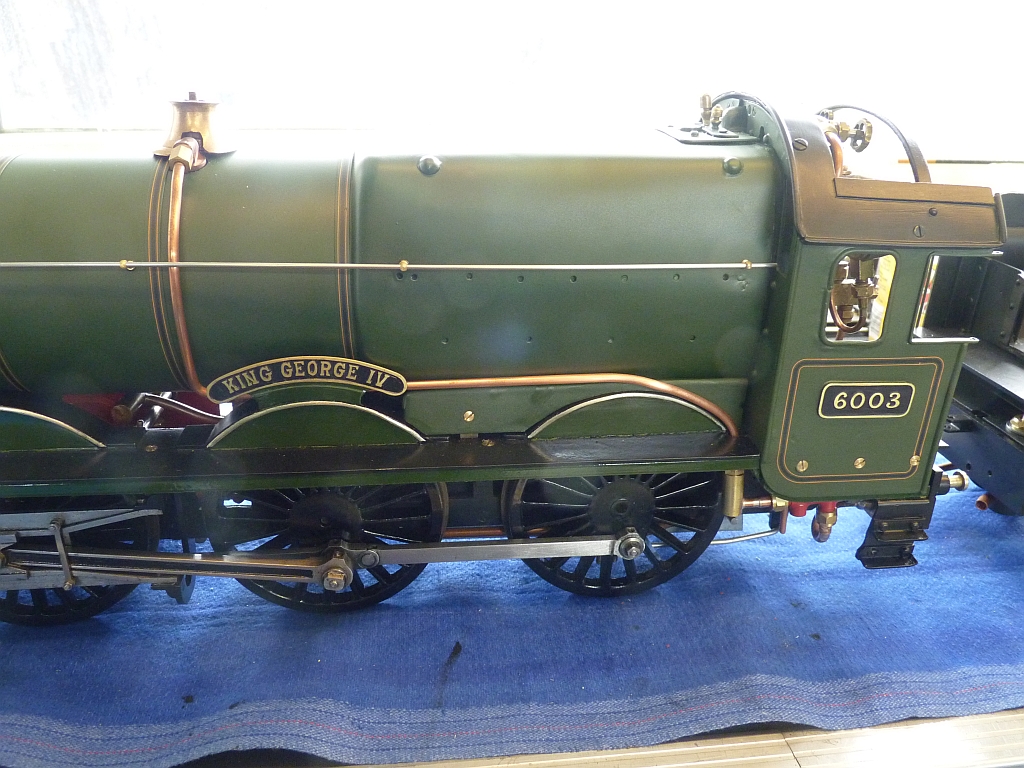
The frames and wheels have been painted and I've begun the fiddly task of refitting all the motion work which I hope to have done in the next week or so.
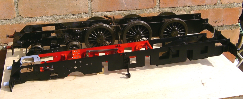
Kingette 1 with Kingette 2 !
29/04/10
Rain stopped play in the garden this afternoon so I washed the front bogie in paraffin and dismantled it. A soak in thinners soon removed what little paint remained! There shouldn't be any work needed on the bogie so a clean up and a coat of paint should have this bit of the job done.
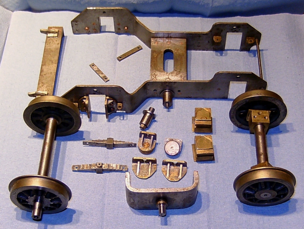
The main parts of the front bogie after stripping off the old paint
Some of the parts that I thought were castings e.g. the front horns, are actually fabrications soft soldered together. The leaf springs on the front axle of the bogie are purely 'cosmetic' and far too stiff to actually work. The actual springing is taken care of by coil springs between the dummy leaf springs and the spring hangers.
Now I've had a closer look at the bogie frame, I am even more certain it is the one made by Mr Marchant and pictured in the Model Engineer article. I still think the loco is possibly the one in Hollingsworth's book but without seeing the original photo it is impossible to say for definite. The only difference I can see is that the loco in the book has different shaped buffers and stocks. The stocks appear to be parallel sided whereas 'Our' Kingette has tapered ones but they could have easily been replaced later. In the photo, the loco is in unlined condition with what appears to be the GWR roundel (shirt button) on the tender which was used between 1934 and 1942. That would tie up with the age of the loco. 'Our' Kingette has been repainted at some time in the past and sports the earlier pre 1934 lined colours with the full Great Western lettering on the tender. This could have been done anytime after the book photo though. There are still traces of the original green underneath the new paint and inside the boiler cladding. It looks a bit bright though compared to the correct green. I suppose what would prove the matter is if the original roundels were still underneath the new paintwork on the tender. We'll have to wait and see!
The weather forecast for the next two days looks very wet so a good excuse to spend the time in the workshop instead of the garden!
08/05/2010
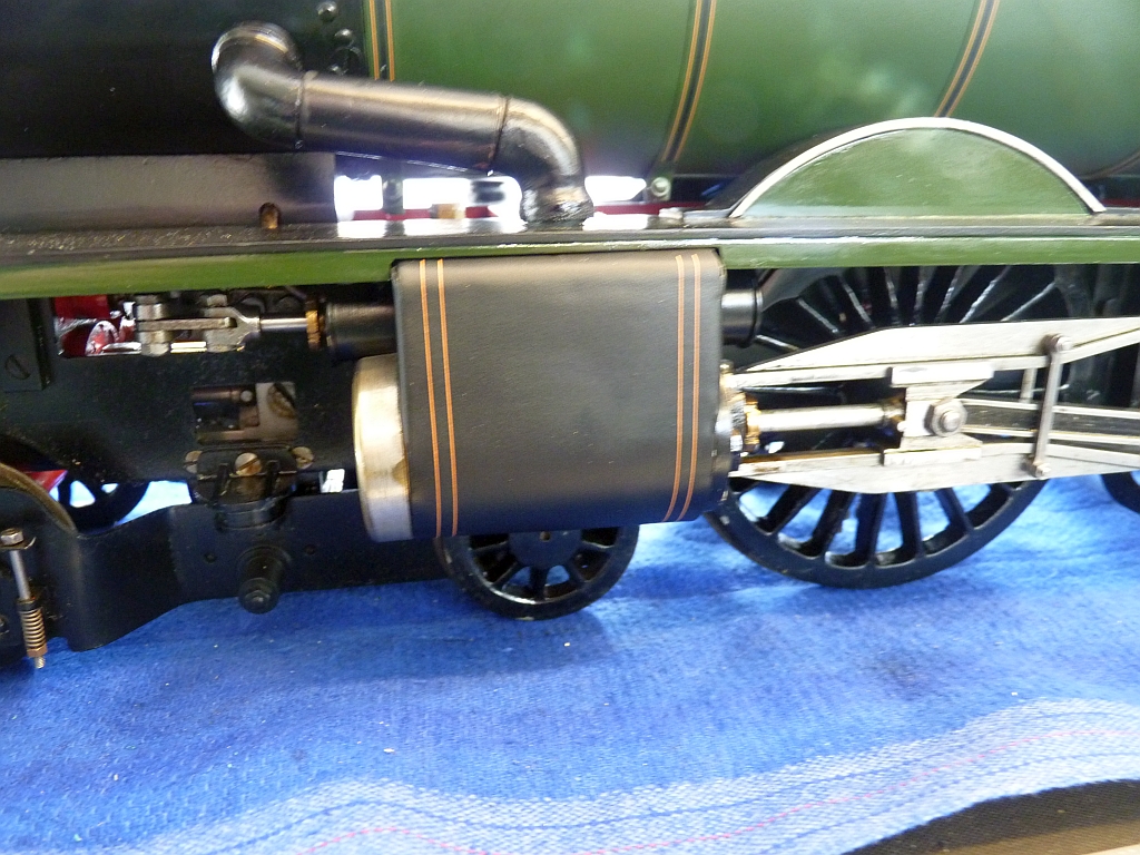
The weather over the last week hasn't been good so more progress has been made on the Kingette. I've fitted the outside cylinders, just the bare cylinder blocks, as it would be very difficult to get at the bolts that fasten them if the inside motion was fitted first. I've replaced the original bolts with studs and nuts, although on assembly I found that one of the studs fouled the exhaust connection to the cylinder. As I didn't want to leave one of the fixings off, I replaced the stud with a hex head bolt with the thickness of the head reduced by about half.
The actual exhaust 'system' is a bit of a nightmare and the connections to the outside cylinders consist of a sort of U shaped manifold bent up from copper tube. This connects via threaded sleeves to right angled elbows fitted into the cylinders. The idea is that you pass the copper pipes through the motion bracket, screw the sleeves all the way on to the ends of the pipes, screw the elbows into the cylinders, and finally partly unscrew the sleeves again until they screw onto the elbows.
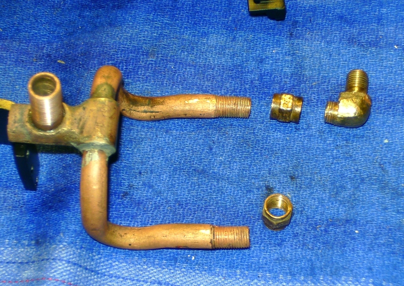
The exhaust pipes and connections to the outside cylinders
I was not very keen on refitting this system as I had visions of not being able to get the threaded joints to seal. I did temporarily do a trial fit but the ends of the copper pipes did not line up with the stubs on the elbows very well and the sleeves were a very poor fit on the pipe and the elbows and would have had to be remade. In the end I decided to replace the sleeves with short lengths of thick wall silicon rubber tubing which merely pushes onto the pipe and the elbows. I reckon this should be ok as there is very little pressure to deal with and the rubber should withstand the steam temperature without problems. It will certainly make connecting things up a lot easier when the time comes!
Once the outside cylinders were in place, the crank axle could be installed along with the inside motion. This was a fiddly job and I could have done with two pairs of hands to hold everything whilst I fitted nuts and bolts etc.! I managed it eventually though and felt that I had reached a bit of a milestone in the rebuild. It was starting to look like a loco again!
The other two axles were fitted without problems and once more I had a rolling chassis.
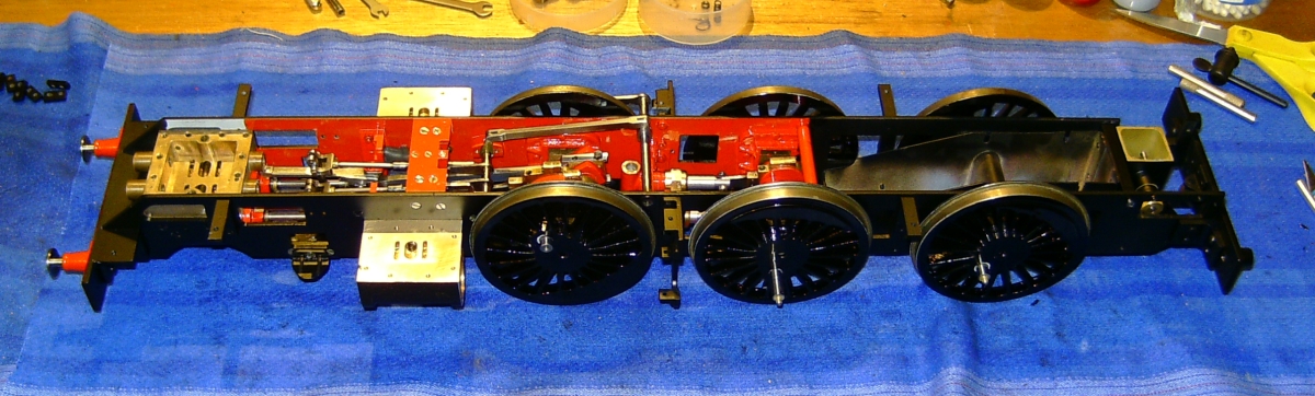
Back on wheels again!
The chassis is a bit stiff at the moment as I haven't oiled anything yet. There's bits of touching up to do on the paintwork and all the screw heads will need painting so I didn't want oil all over everything just yet.
The front bogie has been painted and reassembled but I think the front coil springs will need changing for softer ones. It takes a lot of weight on the front axle to make the axle boxes move!
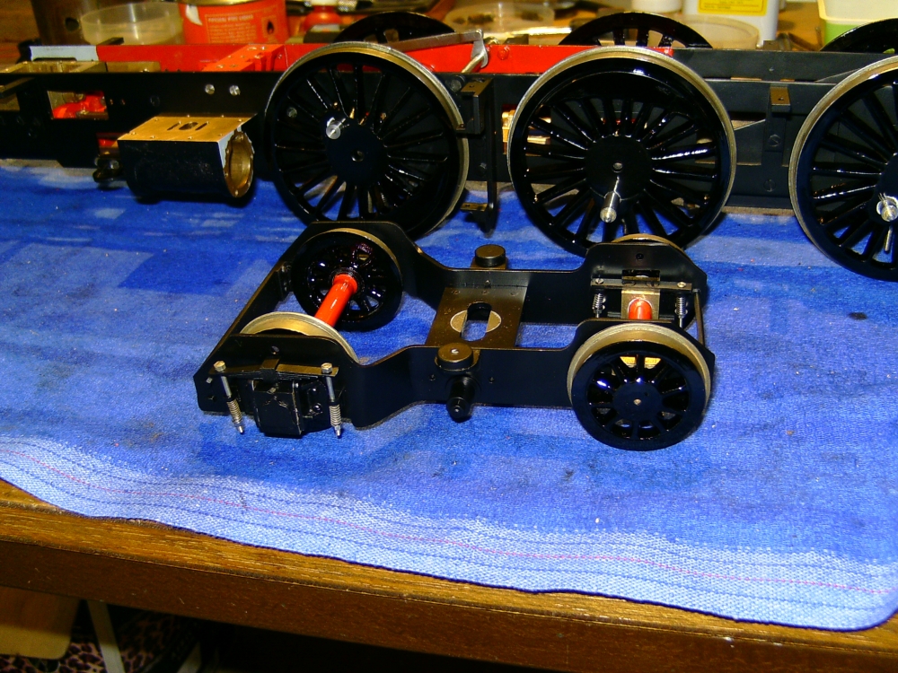
Front bogie reassembled
I've fitted the lubricator but still haven't sorted out how to connect the oil feed to the cylinders. I think the only easy way is to split the main feed into three at the cylinders, one to feed each outside cylinder and one to feed into the steam chest for the inside cylinders. So long as all the pipes are more or less the same length, everyone should get an equal share of the oil.
I think if I were to build one of these locos from scratch, I would redesign the steam supplies to the cylinders and make the outside steam pipes dummies. The real ones are going to be a right so-and-so to connect up.
I was going to fit the top and bottom connections to the axle pumps so that I could refit some of the pipework but realised I haven't got any 3/16" stainless steel balls to replace the old ones so that will have to wait until I've got some. I'm also getting low on nuts and bolts etc. so will need to stock up on those soon.
For something different to do, I started to strip down the tender ready for repainting. I did strip some of the paint off the tender sides but there was no trace of any existing GWR roundel underneath unfortunately. It looks like the old paint on the tender was completely stripped off before the new was applied. Never mind! I did discover that the dummy brake column which is quite shiny and prominent in the Cyril Grose photo is actually nickel silver which had been painted black. It could have originally been left as bare metal as in the photograph.
07/05/12
I can't believe it's two years since I updated this project! Some further work has been done but the sad news is that Tony, the owner and good friend passed away suddenly last November. His widow has decided to keep the Kingette and I have agreed to finish it and then look after it for her and give it a run now and again.
Some time ago I finished all the plumbing for the axle pumps and lubricator and temporarily refitted the boiler. I then gave the loco a run at our club at Whitwick. The loco was very tight (possibly the PTFE rings or lack of oil) and I only managed a very short run before losing steam pressure. I tried a few more times but with the same result. Later I ran the loco on the rolling road at home and it freed up considerably during this running and kept up a good head of steam. The loco then sat around for about a year until the end of April this year when I decided to take a look at the draughting. I decided that the blast nozzle was a bit too big for the cylinder size and also the chimney was much too big in diameter. I made a new blast nozzle and fitted a liner to the chimney to reduce it's diameter. A quick run on the rolling road showed encouraging results so I took the loco to a 2.5" day at the club. I gave it another run towards the end of the day and I managed two good laps before running out of steam. I hadn't bothered to build up the fire as it was getting late so ran out of coal! However, things look promising and I now feel confident to refit the boiler properly along with the cladding. I need to make some new threaded connections for the outside steam pipes so they can be fitted easily. At the moment they are soft soldered together just to get them connected.
15/06/2015
The poor old Kingette has been sadly neglected due to other priorities but I have to admit that my heart hasn't been in it after friend Tony's death. However, his widow decided to sell the loco last year and fortunately another friend was 'persuaded' to buy it. So I have been working on it again over the last 6 months or so and it's now almost finished and ready for a run. I'll just give a quick resume of what has been done lately just to finish this project off. Sorry for the lack of photos but I didn't think to take any at the time. The following may change as I think of more things that I have done and I'll try and add some more photos if I can.
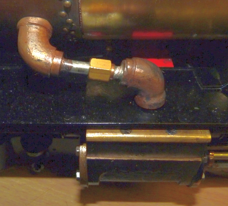
I did make some much better connections for the outside steam pipes which makes it much easier to fit and remove the boiler. Basically I soldered short lengths of 3/16" diameter copper pipe into the elbows on the steam chest and the smokebox and put a threaded union in-between them. I managed to keep the union small so that the steam pipe covers would still fit over them.
The firebox cladding was refitted with great difficulty and many hours spent with filler to get the joint with the barrel looking nice and neat.
A new injector has been fitted along with the pipework. The original feed pipe ran between the frames but I managed to run the new pipe in the correct postion. The original idea was to have the feed clack in the top feed as for the handpump but I decided this wasn't going to be very easy to do. The clacks are 'upside down' and the balls need to be held onto the seats by a spring. That works fine for the handpump but I think I would have needed a really light spring on the injector feed and I couldn't find anything suitable to make such a spring. In the end I abandoned the idea and fitted a separate normal clack at the injector itself.
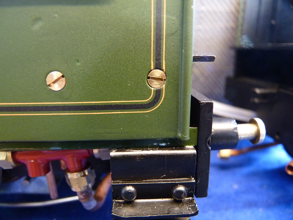
The tender body needed a fair bit of work on it. The top edges were badly bent and needed straightening and the beading was coming away in places and needed resoldering. The original water valve for the injector was scrapped and a new one made. The original was a push pull thing that was very stiff to operate and was only suported by the pipework. I made a nice 90° turn one with a PTFE plug that is bolted to the tender soleplate. Thinking about it afterwards, I should have moved the position of the valve so that it replaced the dummy tender handbrake column. That would have looked better but too late now. I'm not altering it now.
It's then been mainly a case of painting the boiler, cab, tender etc. which is a job I've been putting off as I hate it! Probably because I am not that good at it. Tony had bought some aerosol cans of BR green from a well known model paint supplier but it was absolutely awful stuff and I just couldn't get on with it. The cans put far too much paint on and it just ran everywhere. Eventually I got some brushing enamel from Craftmaster Paints and tried that. It is possible to spray it but I didn't get that good results so finished up brush painting it with more success. It was a case of putting on a lot of coats and rubbing down in-between each one. I finished off with T-Cut and got quite a nice smooth gloss finish. After refitting the boiler to the chassis, the loco was exhibited on our N25GA stand at the Large Scale Model Railway Exhibition in March. Unfortunately, the new owner when he saw it decided that he would like it satin rather than gloss. Much muttering! I could have used satin paint in the beginning rather than gloss!
My friend also wanted the loco lining - even more muttering as I was hoping he didn't! Tony had already bought a set of lining transfers from Fox Transfers so I had a go with those. They recommend putting the transfers on a gloss finish rather than a matt or satin finish as they stick better so at least my efforts with the gloss paint weren't wasted.
I wasn't really sure what to expect with the transfers as the last time I used any was when I was a kid building Airfix plastic kits. I was not looking forward to this at all. Most of the transfers were long lines consisting of a wide black centre with a thin orange line either side with separate matching corners. There were also some single thin lines and two sizes of the BR Lion crest for the tender.
I decided to have a go at lining the boiler bands first as they just needed the straight black lines with the orange edges. The bands were stretched out flat by pinning the ends down to a piece of wood so I didn't have to worry about holding them. (Actually, the boiler bands are much wider than they should be but I wasn't going to make new ones). The instructions say to soak the transfers in warm water with a spot of washing up liquid in it until the transfer can be slid off the backing paper. So I cut the first strip from the sheet and soaked it in the warm water. I must have left it too long as it floated off the backing before I got chance to get it out of the water and it all just got tangled up. That was one strip ruined before I had even started! I had visions of this all being a total disaster. I reckoned I now only had just enough strips to complete the lining so couldn't afford any more cock ups like that.
Fortunately the second attempt went much better and I got the transfer out of the water still on the backing sheet. The instructions say to slide the transfers off the backing sheet sideways rather than lengthways to avoid pulling the transfer and breaking it but I couldn't see that working very well with a long straight line. Instead I held the end of the tranfer line in position on the end of the boiler band and slid the backing out lengthways along the boiler band carefully trying to keep the transfer line in the middle. I think the transfers are actually quite tough and it worked rather well. Where the transfer wasn't central I carefully moved it with a wet cotton bud until it was. That can be easier said than done though as it can be very difficult to move the transfer once it's stuck to the surface! You need a lot of patience for this job and a very steady hand.
The first one came out quite well. Not perfect but acceptable. It got easier as I did the rest of the bands and got used to handling the transfers.
Next I had a go at lining the tender. Not so easy? this time as this involved the curved corners that join the horizontal and vertical lines. The secret is to put the corners on first and then the straight lines. It's extremely difficult to do it the other way around and get everything lined up properly. To get the corners in the right place I made up paper templates and stuck them to the tender sides with masking tape. Getting the corners on without messing them up and getting them square is an absolute nightmare! It's so easy to get one side of the corner folded over and a devil of a job to get it untangled and straight again. I scrapped a few corners but fortunately there were plenty of those to go at.
Once the corners are down and stuck it's relatively easy to put the straight lines on and line them up. Make sure you cut the lines slightly long so that they overlab the corners slightly at the joins. That's much better than leaving a gap. You can hardly see the overlap when the transfer is dry but a gap will be obvious.
![]()
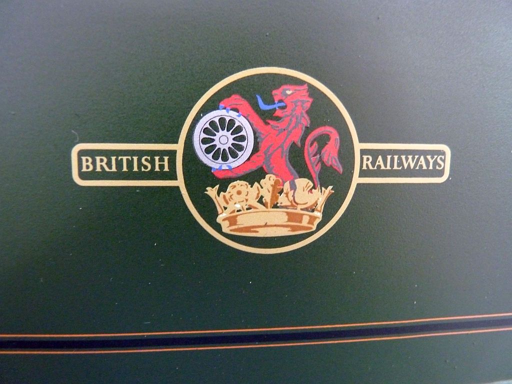
The Lion transfers were relatively easy compared to the lines and corners as they are big solid transfers. Once again, I used paper templates to get them in the right position. Just remember there are right and left hand versions! The Lion should face forwards on both sides (or at least I think they should!)
The next job was to line the cab sides and once again it was a case of put the corners on first (again using paper templates) followed by the lines. The only fly in the ointment with the cab sides was that I had drilled new holes for the fixing screws and of course the lining went over one of the holes! It will be a case of painting the screws after the cab is fitted and then putting a short length of transfer over the screw to fill in the missing piece.
Last but not least were two thin orange lines on each end of the cylinder cladding.
All in all, although I think the job was a nightmare and I was a nervous wreck doing it, I'm really pleased with how the transfers look. I'm not sure I would use them again though.
Once all the transfers were done, the whole lot was sprayed with several coats of satin varnish, both to protect the transfers and to give my friends desired satin finish. I just got some Humbrol satin enamel varnish in an aerosol and that went on lovely. The finish was much better than I expected and I was rather pleased with it, although I think I personally prefer a gloss finish to satin. Some say that a gloss finish makes the locos look toy like but I don't agree with that. It's much easier to clean a gloss finish as well.
It was about this time that I realised that I hadn't fitted the handrail stanchions on the new cladding on the boiler barrel. Oh bother! (or words to that effect) This should have been done before painting. The only way I could fix them now was to drill holes and use Loctite to secure them. Most of the old handrail stanchions were pretty crap so I decided to fit some new ones. I had some 2½" gauge ones from the N25GA but they are really too big and out of scale. Friend David suggested I try Walsall Model Industries which i did and they are much better. The only problem is the mounting spigots are plain and not threaded so they need to be either glued or soldered in.
I really wanted to screw the stanchions into the smokebox like the originals were to make sure at least the ends of the handrails are securely fastened. Unfortunately, the holes in the smokebox were tapped 8BA which is bigger than the stubs on the stanchions so I couldn't just thread them. In the end I cut the heads off some 8BA brass screws, drilled a hole in the end in the lathe to take the stanchion spigot, and then silver soldered the stanchion spigots into them. A bit fiddly but it worked. At least I only had five to do this to.
I also managed to attach the very end stanchion to the firebox wrapper by threading the spigot 10BA and putting a nut behind the wrapper. It was close enough to the edge of the wrapper for me to get at the nut. That just left one stanchion at the front end of the firebox wrapper and two on the barrel to be glued in with Loctite. Hopefully they will be secure enough.
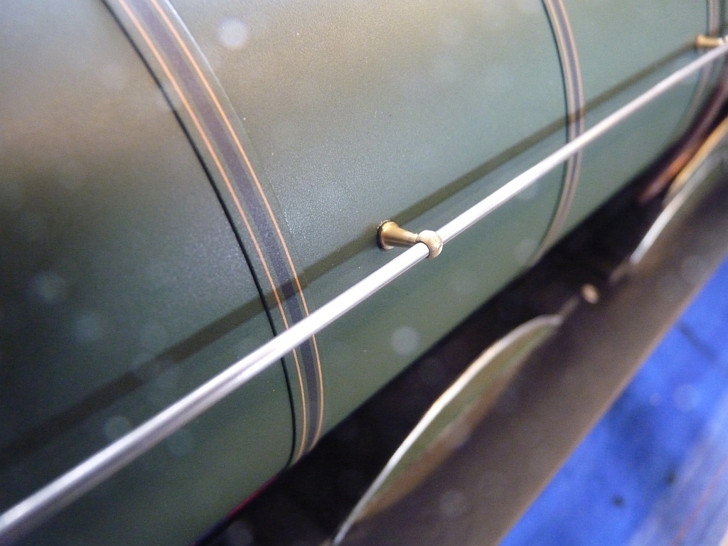
The stanchions from Walsall Model Industries look just right. I believe they were designed for use on Gauge 3 locos and scaled down from full size. The handrails are a bit overscale at 1/16" (1.6mm) diameter. They should be something like 1.2mm diameter but I think for a working model the thicker rails are probably better and less liable to get bent. The holes in the stanchions were for 1.2mm rails but I just opened them out with a 1/16" reamer.
I wasn't happy with the original handrails as they weren't bent very well where they curve across the front of the smokebox so I made new ones. I hadn't any 1/16" stainless steel to make them from but my brother had some copper nickel welding rods which were the right diameter so I used those instead. Actually, he thought they were stainless but they are stamped Cu Ni at the ends. I was surprised at how hard the stuff is. It's very much like stainless steel.
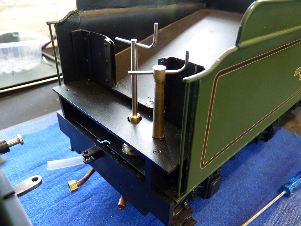
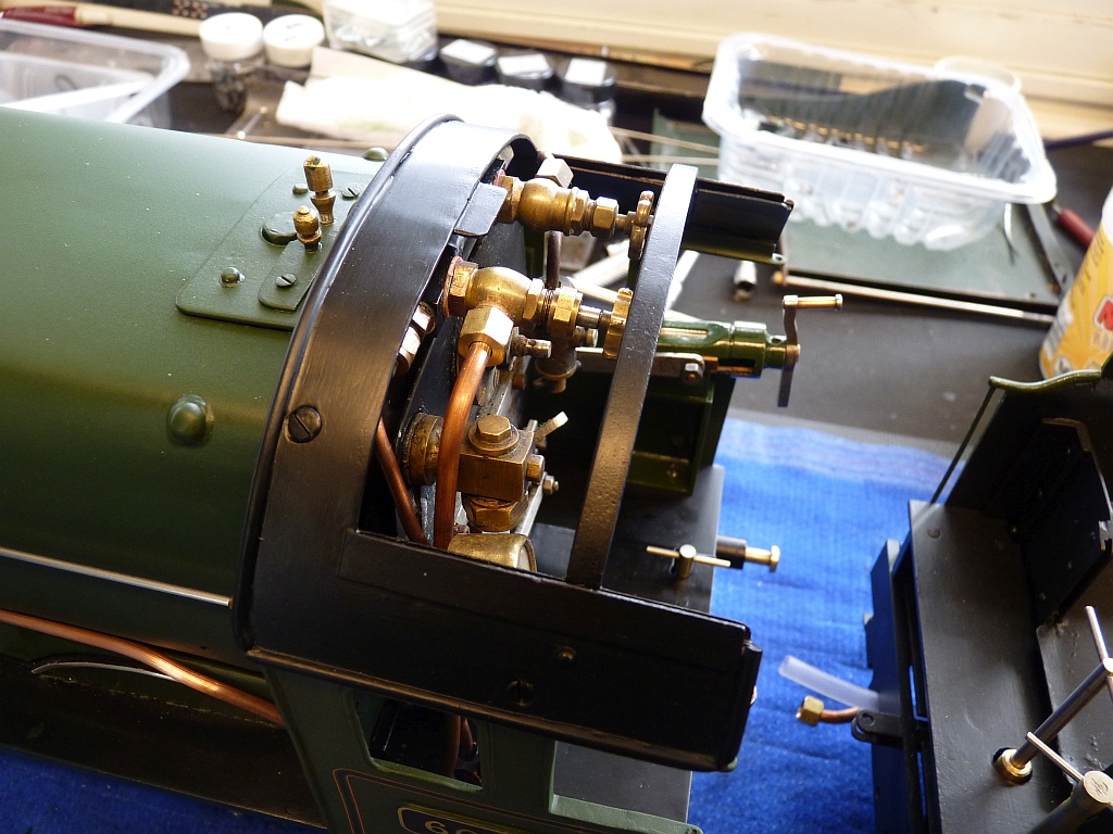
Now the cab roof is on the bar across the opening in the roof is a bit of a pain as it is in the way of the steam valves. Tony was going to get rid of it but I decided to leave it. You can still operate the valves but it is a bit fiddly.
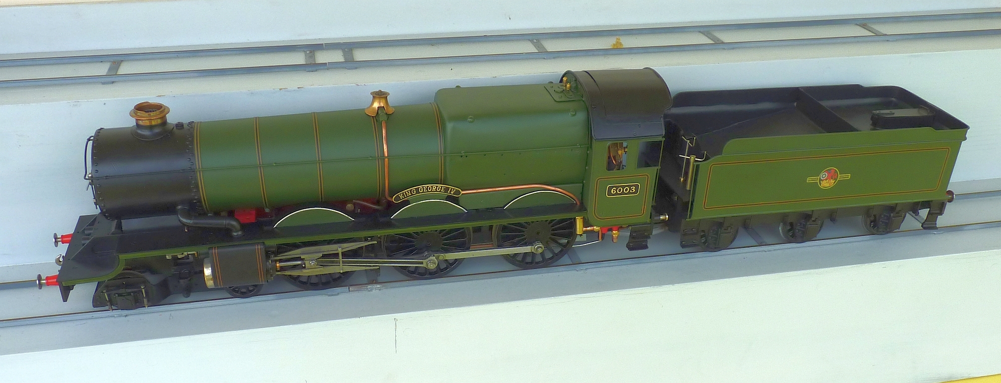
Anyway, here's the results so far:
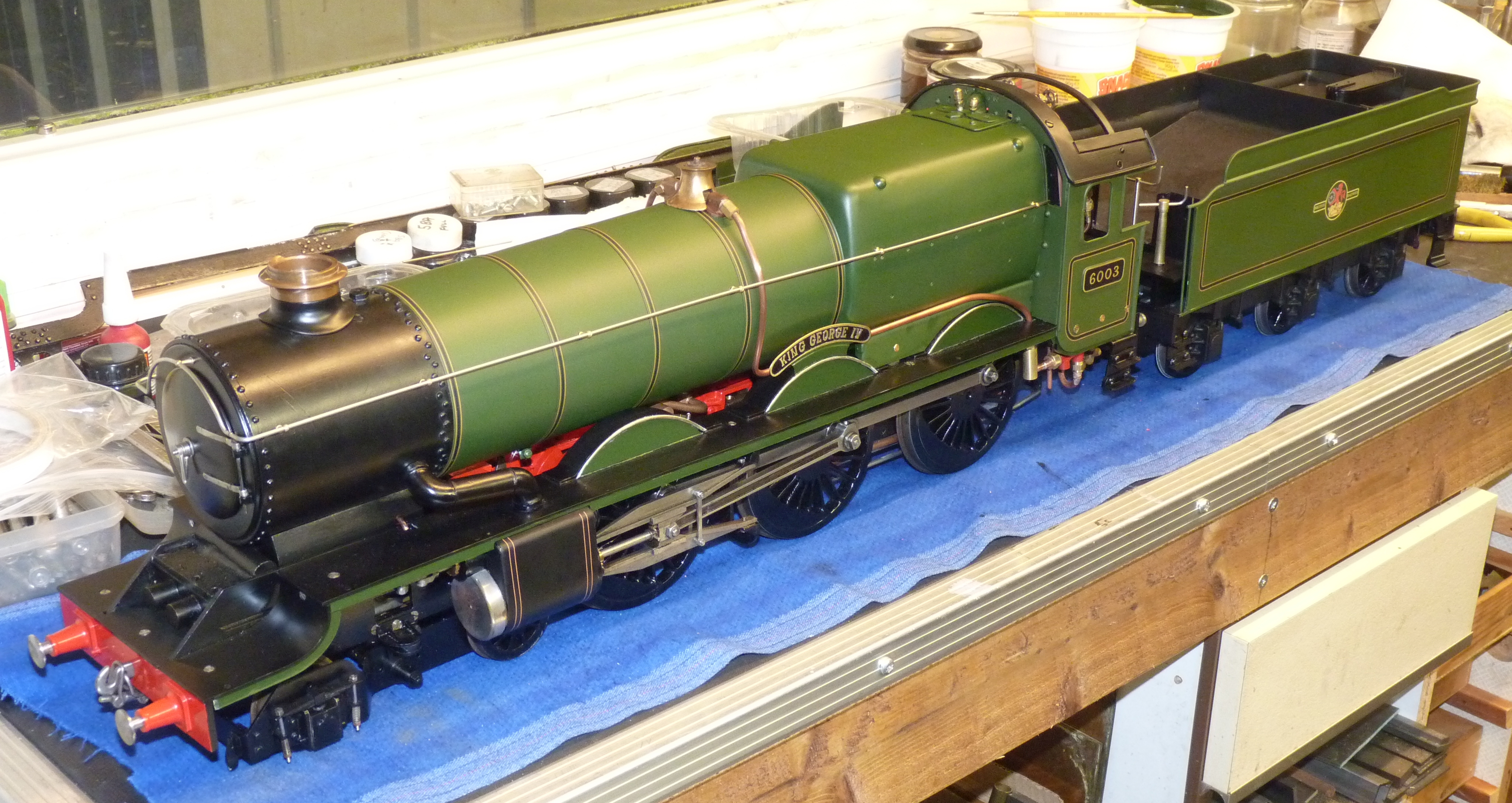
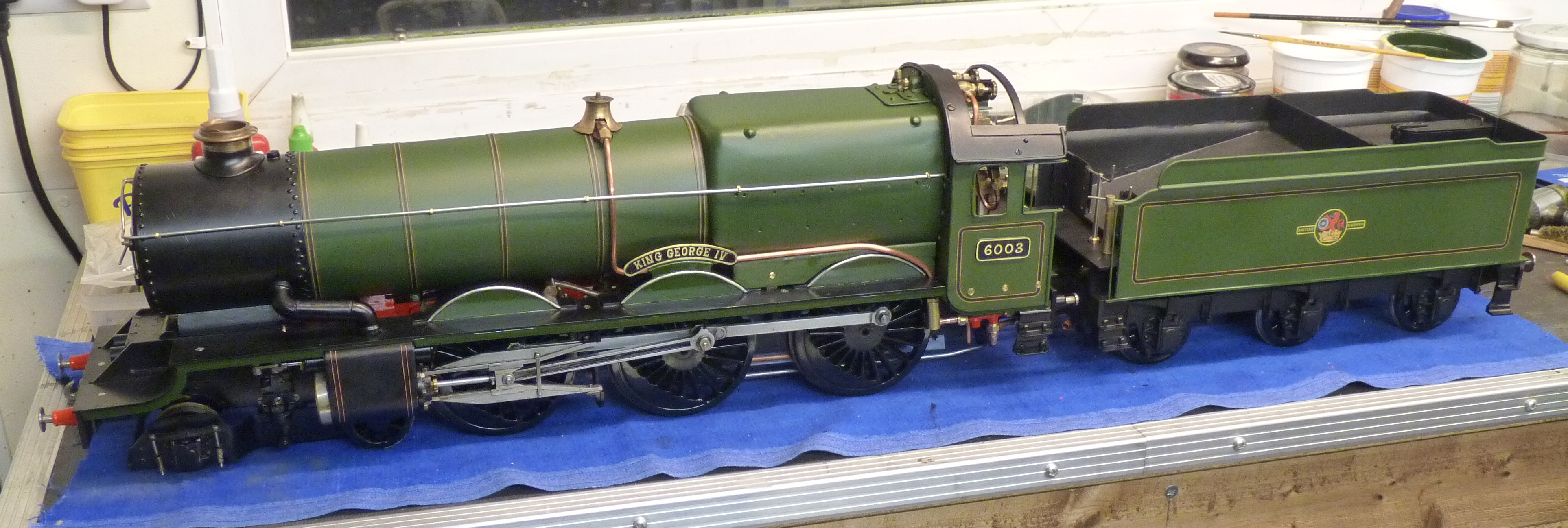
There's still a few little bits to do. The handrails and some screws need painting and then a bit of touching up where the odd chip in the paint has happened but she's nearly done at long last.
Looking at the photos I've just noticed the cab handrails need fitting as well.
We've got a 2½" running day at the club on the 27th and I'm determined she will be there all finished so I can hand her over to her new owner.
27/06/2015
Well, Kingette is finally finished! I took her to the club today for the new owner to look at and I think he's happy. We didn't run her but will do that in a couple of weeks time at a rally at Nantwich.
11/07/2015
Tomorrow is the rally at Nantwich so I decided to steam the King at home today just to check that the injector worked. This was a different injector to that originally fitted and I hadn't got around to testing it yet. The original had never worked at all and Tony had bought a new one so I had fitted that. Unfortunately, it didn't work and just spewed water from the overflow instead of feeding it into the boiler. Good job I did decide to test it today!
I spent several hours messing around trying to get it to work without success. I checked the steam valve and that seemed to have sufficient bore when open and checked that the clack wasn't stuck or the feed pipe blocked. The feed pipe is only 5/32" diameter but thin walled and should be ample for the size of the injector (12oz/minute). I didn't think to check the injector itself as I had temporarily used it on Helen with no problems at all. As a last resort I finally did test the injector on the test rig and it didn't work on that either. Should have checked the injector first! It's possible that it had got a bit of muck in it but the cones were so tight in the body that I couldn't remove them without damaging them. In the end I fitted one of the 8oz ones I had made and used on Helen and that worked perfectly first time.
09/02/2017
My friend who bought the Kingette had his factory unit where he keeps a large collection of 2½"/Gauge 3 locos etc. broken into recently. I found out today that the Kingette loco was one of those stolen. The scum that broke in were only interested in scrap metal so the loco will probably get broken up and finish up down some scrap yard. They missed the tender and a few other bits out of the box that contained the loco such as the cab roof.
So, it's highly unlikely that we will ever see this loco again. I'm as gutted as the owner as I spent so much time restoring it. I hope the scumbags responsible rot in hell!