04/12/2008
Since the last update I've been looking at the inside cylinders and carrying out any remedial work necessary. Again there were a few problems to sort out!
As mentioned previously, the port face was quite worn and this was lapped flat again using 120 grade carborundum paper laid on top of a surface plate, followed by 360 grade. A bit of care is needed here to ensure that the port face is kept flat and not allowed to rock which could give a convex surface. There are still a couple of slight marks left but they will not cause any problems.
The pistons and bores are fine but the piston rods were a mess. One was very 'mangled' at the crosshead end and both were bent, one badly. Both crossheads were loose on the rods and were out of line with the rods as well. The upper slide bars were also bent, probably due to them having a lot of metal removed on the top, presumably to give clearance for the valve gear.
The next job then was to make new piston rods. The old rods were screwed into the pistons and were a very tight fit. As I didn't want to grip the outside of the pistons and risk damaging them, I drilled a couple of shallow holes in the ends so that I could turn the pistons with the pointed ends of a pair of pliers whilst gripping the rods in the lathe chuck. Even so, I had to heat up the pistons with a blow torch to get them off! It is possible that at some time they had been fixed with Loctite I suppose.
Two new rods were made from stainless steel and threaded to screw into the pistons. The pistons were then screwed on, tightened up using the pliers in the shallow holes again and then the ends of the rods were faced off flush with the end of the pistons. Before final assembly, I'll punch the ends of the rods to stop them unscrewing again.
The crossheads are a bit rough but I did not fancy making new ones so I cleaned them up as best I could and reamed out the bores for the piston rods. After reaming, the bores were slightly oversize but at least they were now in line with the slide bar grooves! The crossheads have also had quite a bit filed away to give clearance for various other bits. Obviously, the original builder had problems getting everything to fit in with sufficient clearance. I wonder if this is due to the original design or just this particular loco? I think as I go along I'll make a few drawings to the published dimensions and see if there are problems with the original design. A member of the 2½" Gauge Association is going to redraw the original plans for Kingette so any problems found now will help him later.
The next problem was the slide bars. These were carefully straightened and bolted in place on the cylinder end covers. They finished up far from parallel to the piston rods and this proved to be because the ends of the bars that bolt to the covers had been filed to adjust the gap between the bars and the piston rods. Unfortunately, they had not been filed square and this was causing the problem. This was remeded by setting the bars up in the lathe tool post and milling the bolting faces square again. While I was at it, I also took a skim off the bolting faces on the cylinder covers to make sure these were square as well. This improved the alignment of the bars considerably but does mean that shims will now have to be fitted between the bars and the cylinder covers to get the correct fit for the crossheads. Finally, the working surfaces of the bars were given a rub on some fine carbrundum paper to remove any roughness. It looks to me as though they have suffered from a lack of oil as there was evidence of galling on the surfaces of the bars and on the slots in the crossheads.
I was now in a position to refit the crossheads to the piston rods. The pistons and rods were refitted through the cylinder end covers using O rings in the glands rather than the original graphited yarn packing. The O rings fitted nicely in the original threaded bores in the cylinder end covers when the glands were screwed in as far as they would go. The slide bars were then fitted to the covers using suitable shims and the crossheads fitted. As mentioned, the bores in the crossheads for the piston rods were slightly over size so once I was happy that the crossheads were true and square to the bars, a drop of Loctite was put on the rods to run into the crosshead bores. After leaving this to set, the crossheads were firmly fixed to the rods and they were then drilled and reamed for new taper pins to fasten them securely.
The last job for now was to repack the piston grooves. I had already decided to use PTFE rings after the success using them on Helen and these were made exactly the same with two split rings per piston with the ring gaps at 180° apart to reduce leakage.
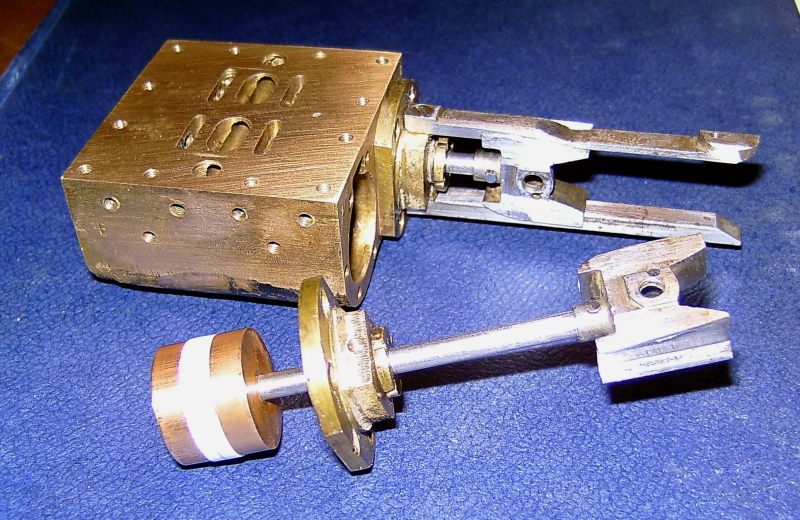
Inside cylinder and pistons with new piston rods and PTFE rings
06/12/2008
Next task was a repair job to the inside motion plate. This is the usual steel plate and brass angle fabrication but is considerably cut down compared to the drawings in the construction series. They show a full plate with cutouts for the slide bars and valve rods but this one has all of the centre removed and is just a U shape. Unfortunately, this weakens it considerably and it won't help stiffen the frames much like it should do. Again, I presume it has been altered to clear the valve gear.
When I removed it from the chassis, one of the little brackets to which the bottom slide bars fasten had become detached from the motion plate. When I looked closely, both sets of these bottom brackets were only soft soldered in place so it was no wonder one had come loose! The top brackets were secured with a rivet as well so these were ok. I obviously could not use silver solder to refix the bracket so I had to stick with the soft solder. However, I drilled and tapped the motion plate and the brackets and fitted a couple of 10BA screws through the lot to make sure they did not fall off again!
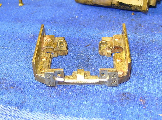
The inside motion plate with the slide bar brackets resoldered and screws fitted.
The two holes in the edges of the motion plate are for the exhaust pipes from the outside cylinders to pass through.
I think it might be a good idea to have a look at the inside valve gear next before starting to reassemble the frames as I only want to do this once! I have a feeling that there may be other 'horrors' awaiting!
12/12/2008
I've started on the valve gear and so far it doesn't look too bad! The eccentric straps had quite a bit of play on the eccentrics but this was removed by simply milling about 0.01" off the bolting face of the 'loose' strap to remove the ovality of the bore which was causing the play. Virtually all the wear on straps like these is on the front and rear of the bore where the load is the greatest. The top and bottom of the bore hardly wear at all. The eccentric straps for the water pumps will no doubt require the same treatment when I get to them.
The expansion links are in two parts, one side has the curved slot for the single die block to run in and the other side is basically a flat plate to carry the other pivot pin. In this case, the plain side has been machined from the solid to form spacers at the top and bottom to leave a gap for the radius rod to pass through. The two halves are held together with 12BA csk screws. The two pivot pins run in bronze bushes in the fabricated expansion link bracket.
There is evidence of wear in the expansion link slots but these appear to have been hardened so it would be difficult to clean up the slots to true them up again. It would probably mean having to make new links which I want to avoid. I think with new die blocks they should be ok for a few more miles yet.
The pins which fasten the links to the eccentric rod forks were badly worn and a very sloppy fit in the links so these had to be renewed. The originals seem to be an odd size and are something like 2.5mm in diameter. It is possible to get 2.5mm silver steel but the bores in the links were also a bit worn so I needed to go up a size. The nearest I've got is 1/8" diameter but I wasn't sure if I would be able to ream out the holes in the expansion links due to them being hardened. As it happens, the links were not as hard as I had thought and I managed to drill out and ream the holes in the mini mill to ensure that the new holes were perfectly square to the links. The holes in the forks of the eccentric rods were given the same treatment and then new pins pressed in. These are a press fit in the forks but a running fit in the expansion link hole. The new 1/8" pins have a larger bearing surface than the originals of course so hopefully will wear better.
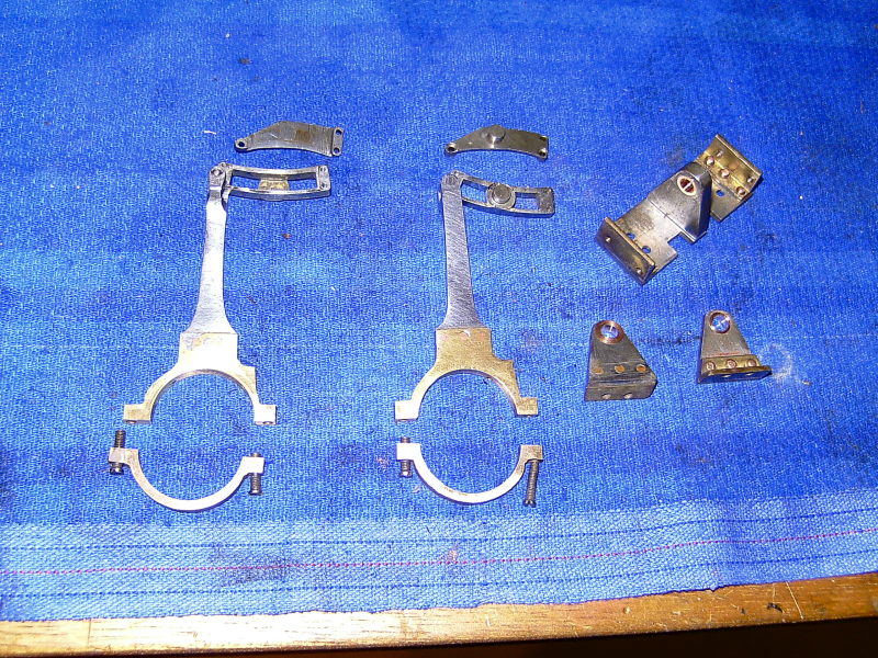
Expansion links, eccentric straps, and link brackets
I find that the way to get the right press fit is to not put the reamer all the way through the fork, leaving the pin a push fit in the first hole in the fork but a press fit in the second. If the pin is a tight fit in the first hole, you are liable to bend the fork when you press in the pin.
Talking of making pins for valve gear etc, I find that when using reamed holes and silver steel pins, the pins are always much too tight for a running fit. I suppose this figures really as a 1/8" reamer should give a 1/8" diameter hole. Silver steel is very accurately made so 1/8" diameter will be the same size as a 1/8" reamed hole - giving no clearance! The way I deal with this is to lap out the hole after reaming using some fine carborundum powder mixed with oil on a piece of the same silver steel as used for the pins. This takes out a few tenths of a thou in the bore and is done until the real pin is a nice running fit.
Back to the job in hand:
The bushes in the expansion link brackets were a very sloppy fit on the link pivot pins so the old bushes were knocked out and new ones turned up from bronze bar and pressed in.
I then did a trial assembly of the expansion link assembly in the frames. The new bushes in the expansion link brackets needed 'easing' a little to allow the links to swing freely and also the eccentric rods needed a bit of 'tweaking' to align the straps with the eccentrics properly. After this, the wheels rotated freely with everything bolted up.
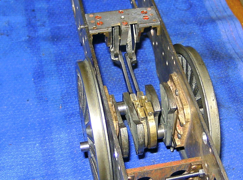
Trial assembly of the expansion links, brackets, and eccentric rods
Next thing to look at is the radius rods. These are different to those described in the construction articles in that the originals were suspended by swing links from the lifting arm whereas these have slots in the ends which run on a pin on the lifting arm. Personally I prefer this method as the link method causes the radius rod to move up and down slightly as it moves backwards and forwards. This means that the die blocks also move up and down slightly in the expansion link slot causing unneccessary wear.
These rods are built up from three pieces. The end section with the slot and the die block is made from flat strip but the actual bit that connects to the valve crosshead is a length of round rod threaded at both ends. The two are joined with a turned 'connector' with threads at each end. These two threads are offset slightly, obviously to move the rod over to align with the valve crosshead.
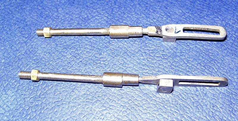
The built up radius rods
I presume that the valves can be adjusted by how far the threaded end of the rod is screwed into the crosshead. This will be a nightmare to do as it will probably mean dismantling half the valve gear to be able to turn the rod! It would be better if the valve rod was screwed into the crosshead but instead it is held with a taper pin. I can see that the valve setting is going to be fun!
One odd thing is that the slot in the end of the radius rod that runs on the lifting arm pin is not straight and is slightly curved (you can just about see this in the picture above). This has been done deliberately but I can't fathom out why. This curved slot will have the same effect as suspending the rod with a swing link and will cause the rod to move up and down as it moves backwards and forwards, again causing wear on the die block and slot. I'm tempted to machine it out straight and fit an oversize pin on the suspension arm. I wonder if the original builder thought that this slight up and down motion was a necessary feature of the valve gear design?
The die blocks appear to be hardened steel and run on pins rivetted to the radius rods. One is not too bad a fit but the other is a very loose fit on its pin and also in the expansion link slot. I may make two new ones from PEEK. I used this for the die blocks on Helen and they seem to be holding up well.
Not connected with the valve gear, but there was an article on King Edward VIII by Peter Rich in a recent Model Engineer. The article had some general arrangement drawings of the loco so I scanned them and then enlarged them to full size for 2½" gauge. It's interesting to see that the frame cut outs which I thought were on the big side are actually about right. The wheel bases on 'our' king are also about right but the frames are an inch longer than the scale length. This seems to come from the rear end, presumably to give more room on the footplate! The majority of the dimensions however seem quite close to scale which is unusual for an LBSC design. Even the boiler is very close to scale and not grossly oversize. The only thing which really sticks out is that the cylinders seem to be much longer than they really need to be. The pistons on this engine are over 1/2" thick which seems excessive. By reducing them to 3/8" it would be possible to reduce the cylinder length by at least 1/8" which would help the appearance.
14/12/2008
I decided to remake the slotted ends of the radius rods and fit them with new pins and die blocks. The new ends were made from a couple of lengths of 1/4"x1/16" BMS bar which were soft soldered together to mill the slot and drill the holes for the die block pins. (I would have prefered to use gauge plate rather than mild steel but I had no suitable size in stock). The two were then separated and the ends turned down and threaded 6BA to fit into the joining block. The slots were then case hardened to resist wear a bit better.
The die block pins were made from short lengths of 1/8" silver steel threaded 5BA at the end and screwed into the holes in the slotted bar. They were then given a touch of silver solder to hold them securely.
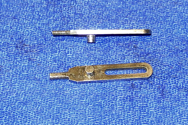
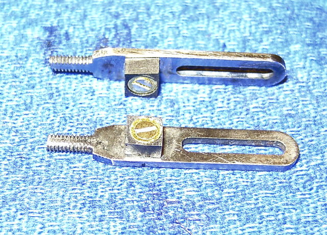
The new slotted ends for the radius rods
The die blocks are 1/8" thick and I decided to go with the PEEK again as it's so easy to work with. They were made in exactly the same way as for Helen (page 21). A piece of 10mm PEEK bar was chucked, drilled, and reamed 1/8" dia. to fit the die pins and two 1/8" thick slices parted off. These were then shaped using the rotary table in the MicroMill using the same fixture I had used for Helen.
To set the correct radius for the die blocks, I firstly mounted the rotary table on the milling table and then fitted a centre in the rotary table and a needle in the mill chuck. It was then an easy job to wind the milling table across until the distance between the centre and the needle equals the radius of the centre of the die block.
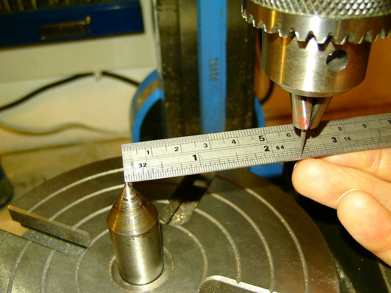
Setting the radius for the die block
The plate on which the die blocks are mounted was then bolted onto the rotary table with the centre of the bolt holding the die block in line with the needle still in the chuck.
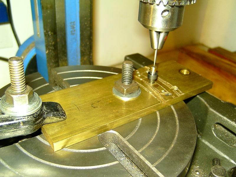
Setting the centre of the die block in line with the needle
The die blocks were then machined to fit in the expansion link slots and then trimmed to the right length. I actually made them a bit on the tight side and then eased them with a fine file to get the right fit. The fit was not perfect all the way along the expansion link slots as the slots had worn unevenly but they are not too bad. They are certainly a much better fit than the old ones!
It was at this point that I realised that the die blocks had to be held captive on the pins. The slots in the expansion links are open on both sides (unlike Helen's) and it would be possible for the die block to come off the pin. The originals had a chamfer at the end of the pin which had been rivetted over slightly to hold the die block in place. I did not fancy repeating this so shortened the pins, drilled and tapped them, machined a recess in the die blocks, and then fitted a 10BA screw and washer to hold the die block in place. A bit fiddly but did the job.
Die blocks fitted and retained by a screw and washer.
The next part of the job was not so easy and when I came to remove the old slotted ends from the joining block, both snapped off leaving the threaded part in the block! I was half expecting this to happen but it was still a pain. The only way to get around this was to drill out the old bit and retap the block.