15/12/2008
I could now reassemble the radius rods and fit the forks onto the ends which connect to the combination levers. As mentioned before, the radius rods screw into the forks and are locked in place with a nut and I presume this was meant to be the adjustment for setting the valves as there is no other.
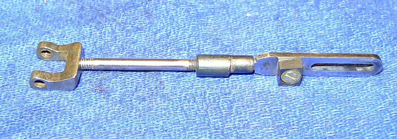
Radius rod with fork.
It then dawned on me that this is incorrect as the radius rods must be a certain length i.e. the distance between the pivot in the fork and the centre of the die block must be equal to the radius of the middle of the expansion link slot. Therefore this could not be adjustable and could not be used for adjusting the valves without upsetting the whole geometry of the valve gear.
I checked the actual distance between the centre of the fork pivot and the centre of the die block on both rods and even with the forks screwed as far out as possible, one rod was 1/16" too short and the other nearly 1/8"! The original valve events must have been way out as the incorrect radius rod lengths would have caused the valve positions to move as the reversing arm was raised and lowered to alter the cut off. The loco would have only run properly when the reverser was in the position used to originally set the valves. Altering the reverser would have thrown the timing right out.
The only thing was to make the radius rods the correct length and this was easily done by making two new threaded rods for the front section of the rods and adjusting the forks to give the correct distance between the fork pivot and the die block. That has solved that problem but introduced another in that there is now no easy means to adjust the valves. The valves are driven by a favourite LBSC method of filing flats either side of the valve rod which fit into a narrow slot in the top of the valve, so no adjustment there. To my mind this is a pretty poor method and leads to rapid 'slop' in the drive resulting in lost motion. The ends of the valve rods are also pinned into the valve crossheads rather than screwed in so no adjustment there either.
I think the best way to go is to alter the method of driving the valve and making the valve position adjustable on the valve rod. This is normally done by slotting the valve crosswise and having a rectangular 'nut' on the valve rod which fits in the valve slot. The 'nut' is clamped onto the valve rod by a grub screw and the valve adjusted by moving the nut along the rod. This modification will also enable the timing of the outside valves to be easily adjusted. At the moment the only way is to alter the length of the little link that connects the valve rod to the rocker shaft. I'll have to check first though that there is enough 'meat' in the valves to enable this to be done.
As a matter of interest I quickly reassembled one set of the valve gear and fitted the valve chest and the valve to see what the valve timing was actually like now I've altered the radius rods. As expected, the timing is miles out and in full gear, one port opens nearly 1/16" more than the other!
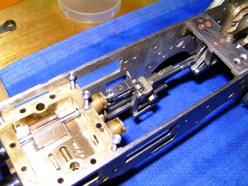
Trial assembly of one set of valve gear
As I expected, there is quite a bit of play between the flats on the valve rod and the valve itself resulting in quite a bit of lost motion.
22/12/08
I haven't achieved much since the last update as I've succumbed to the usual winter cold and haven't felt like doing a lot!
I've had a look at the valves with regard to changing the method of driving them. Unfortunately, the valve rods are very close to the port face and there is not enough depth in the valves to machine a cross slot to take the usual rectangular nut. Machining a suitable slot would break into the exhaust cavity in the valve. So much for that idea! Another idea I'm considering is fitting two nuts, one at each end of the valve, driving on the ends of the valve. This will avoid the need to machine a slot in the valve itself. There would be enough room to fit these in between the ends of the valves and the inside of the steam chest and they would not intefere with the travel of the valve in full gear. The only other way is to thread the ends of the valve rods and screw them into the valve crossheads which would mean altering the crossheads to be able to thread the bosses. I would have to retain the present method of driving the valves using the flats on the valve rod though which I am not keen on doing. Ho Hum!
One thing I noticed when I temporarily assembled the valves onto the rods and fitted the valve chest in position, was that the ends of the valves are not parallel to the steam ports in the cylinders i.e. they are slightly skew to the ports. The slots that take the valve rods are obviously at a slight angle to the valve body which means that the ports do not open evenly all the way along, they open at one end first. Not good for getting the steam into the cylinders quickly at the beginning of the stroke. I have measured the valves and they are slightly too long so it will be easy enough to true them up so that the ports open as they should.
Incidentally, the ME articles show the valve as far too short. The length is given as 21/32" which gives a lap of only 1/64" which will not give the steam much chance to be used expansively. I would suggest that the lap should be 1/16", making the valve length 3/4". This will give much better steam consumption. The original builder of 'our' Kingette must have realised (or been told) that the published dimension was wrong. However, he went a bit the other way and made the lap 5/64" which is perhaps a bit excessive.
The ME drawings for the valve show 1/64" exhaust clearance which is unusual. Exhaust clearance is supposed to make for a freer running engine as the exhaust port opens slightly earlier allowing the steam to escape at the end of the stroke a bit earlier but whether that is any advantage in 'our' sizes is debateable. Modern designs tend not to use it.
As a bit of light relief (boy, do I need some!) I temporarily fitted the reverser to the frames along with the weighshafts and reach rod to see what the valve travel was like in forward and reverse gear. Whilst it is possible to get full travel in forward gear, it is not possible to do the same for reverse and it looks as though the reach rod is too long and will need to be shortened.
The reverser is a proper screw type and is mounted on top of the lubricator which acts as the stand. The articles call for a lubricator mounted on the running boards but our builder fitted it in the cab instead. It's a huge twin ram pump driven by a rod from one of the axle pump eccentrics and probably wouldn't look out of place on a 7¼" loco! It's certainly bigger than is usually fitted to a 5" gauge.
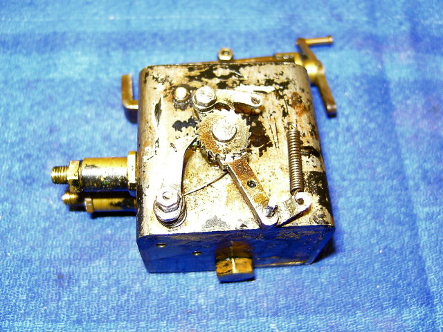
The lubricator
It really is a bit of a monstrosity for a loco this size and I would be tempted to replace it with something a bit more suited and a lot neater!
Whilst pondering the valve problem, I've started work on refurbishing the various pivot pins in the valve gear. Fortunately, it seems to be the old pins that are worn rather than the holes in the linkages so it's mainly a case of just making new pins. Where possible, I'm going to use the type of pin I devised for Helen i.e. a hollow silver steel pin with a bolt through it secured with a nut. On this loco though, most of the pins are only 3/32" diameter so the bolts will have to be 10BA. A bit fiddly!
The first ones to tackle are those for the union links connecting the bottom of the combination lever to the crosshead drop arm. The links consist of two thin plates either side rather than a solid link slotted at each end so they are a bit flimsy. The 'words and music' say to make them 1/16" thick but these are only 1/32".
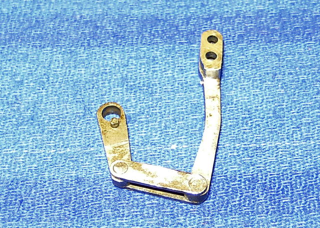
Union links with old pins
The old pins were just rivetted over at the ends to hold them in place so they had to be drilled out to remove them. They were very loose in the holes in the combination lever and drop arm, especially in the drop arm. This hole is very oversize so I will have to either bush it or fit an oversize pin.
28/12/08
I hope everyone has had a good Xmas and Santa has delivered something useful for the workshop!
I've had a bit of a break from the Kingette over Xmas but yesterday I spent a few hours looking at the design of the original valve gear as described in the ME articles. I've been drawing it out in CAD and putting the figures into Charlie Dockstader's valve gear program. It appears that some improvements can be made to the valve events by 'tweaking' some of the dimensions. The original dimensions cause a few problems with unequal valve events at each end of the cylinders and also some of the linkages seem to be shorter than they should be. I think this is a classic case of a designer describing how to build a loco without having built one themselves first!
The first problem with the original design is with the radius rods and their suspension links. The ends of the radius rods are suspended from the lifting arms on the weighshaft by 1/16" thick links on each side of the rods, similar to the double link between the drop arm and the bottom of the combination lever. The distance between the die pin and the pivot point for the suspension links on the end of the radius rod seems to be too short and apart from the fact that quite deep cutouts need to be filed into the stretcher carrying the expansion link brackets to clear the ends of the lifting arms when they are at the highest point, there is not enough clearance between one side of the radius rod and the expansion link bracket for the suspension link to fit in. The gap is 1/32" but the link is 1/16" thick! I wonder if that is why the builder of 'our' Kingette dropped the idea of the suspension links and went for the slotted end for the radius rods running on a pin? (Interestingly, the clearance slots are present on the stretcher even though they are not needed in this case). I think the way around that problem is to make the radius rods at least 7/32" longer and move the weighshaft back by the same amount. This brings the suspension links clear of the expansion link brackets and avoids having the clearance slots in the stretcher. I haven't checked yet though that this would cause other problems.
When I drew out a general arrangement of the valve gear it was also apparent that the union links are far too short and the combination lever would be at an angle when the piston is at mid stroke when it should be vertical. The links need to be increased in length from 7/16"(0.4375") to nearly 9/16"(0.555"). Also, the combination levers are drawn as straight but they will then foul the nut holding the drop arm on the end of the gudgeon pins. On our Kingette, the levers are 'banana' shaped to give the necessary clearance (see photo above) and the union links are 19/32" (0.594") long.
Putting all the dimensions into the valve gear program showed other problems. The swing of the expansion link is not equal either side of the mid position which points to the 'backset' of the driving pin not being correct. (Backset is the amount the driving pin from the eccentric rod lies behind the pivot point of the link and is required to equalise the swing)
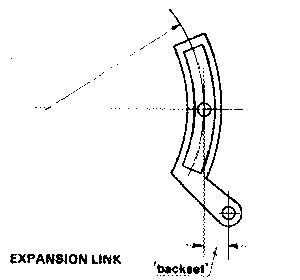
On the Kingette drawings, the backset is shown as zero i.e. the driving pin is in line vertically with the link pivot. On Kingette, the driving pin is on the centreline of the motion and I assumed (as perhaps did LBSC) that backset is not necessary in this case, only if the driving pin is above the centreline of the motion. Obviously this is not the case and playing around with the figures showed that a backset of about 1/8" (0.125") was necessary to equalise the swing. Changing the backset also affects the length of the eccentric rod and this needed to be altered so that the link was vertical when the crankpin was at front dead centre and rear dead centre. Adjustments like this are dead easy to make and check using the program.
I must admit that having used Charlie's program for some time now, I am a bit bemused now at some of the hit and miss methods described for setting the position of the return crank and finding the length of the eccentric rods which involve trial and error using dividers etc. There is only one correct position for the return crank i.e. the one that gives the correct valve travel and this can be determined by drawing or computer programs. It's then easy to make a jig to set the crank once and for all. Don Young always did it like that. Similarly, it's easy to determine the correct length for the eccentric rods. I suppose the problem can be that the valve gear may not have been designed correctly in the first place or some parts not made exactly to plan so I can see the reason why some people suggest making an adjustable eccentric rod to begin with.
I next looked at the swing of the combination lever to see if that was equal either side of the vertical position. There didn't seem to be a way to do this with the program so I resorted to CAD for this. Drawing everything out showed that there was a difference in the swing, although only a couple of degrees. Playing around with dimensions showed that increasing the length of the drop arm from 1/2" to 9/16" soon sorted that out. Out of curiosity I measured the length of the drop arms on the crossheads and they have been lengthened to 9/16". Obviously someone else has had a look at the design of the valve gear and made a few alterations to the proportions. That gives me a bit more faith in my own ideas!
Putting all the revised dimensions into the program gave valve events that are very good with virtually no difference between forward and reverse gear and equal cut offs at each end of the cylinder.
I would just say that the differences between the original valve gear and the revised are not huge and I am sure that a loco made to the original dimensions may run perfectly well but nevertheless, the valve gear can be improved. I think the main problem with the original is that some bits won't fit without some modification and some of the dimensions do appear to be wrong.
I can see me finishing up doing a full set of drawings incorporating any modifications if only for future reference!
Another quick update. I've just been drawing out a cross section of the original valve gear with the combination levers and slide bars and I think I realise now why the valve gear on 'our' Kingette differs so much from the original design. Basically, it is virtually physically impossible to build the valve gear as originally designed - there is just no room to fit it in! The bottom of the fork of the combination lever fouls the top slide bar and there is no way it can be made to clear without serious surgery on both the combination lever and the slide bar which would leave little metal left on either. Also the inside of the combination lever will foul the crosshead unless it is made much thinner.
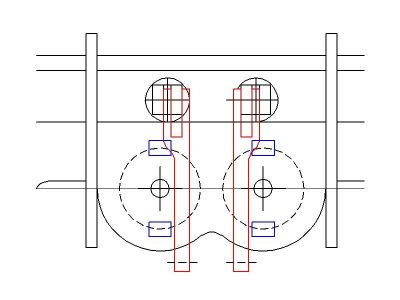
Drawing showing the problem with the combination lever fouling the top slide bar
I think this explains why the top slide bars have had so much metal removed and the design of the combination lever has been changed. The original builder has tried to build the valve gear as described, filed bits off everywhere to try and get the necessary clearances, and finally given up and started again. This could explain why the stretcher for the expansion link brackets has the clearance slots for the lifting links. It was probably originally built with the lifting links rather than the slotted radius rods.
Basically, the valve gear needs completely redesigning if the drawings for Kingette are going to be made available again so that new locos can be built. It will be no good just copying the existing drawings from the ME articles. One thing which would help matters considerably would be to move the valve spindles closer together which would move the combination levers further from the slidebars. I think they could be moved inwards by 1/16" without causing problems, in fact this would put them almost the correct scale distance apart.
14/01/09
Although it's over two weeks since the last update, I have been doing a bit on the King.
I've been 'doodling' with drawings for the valve gear for the original King and trying to come up with a design that will actually fit in the space available! I think I'm getting there but came across another 'clanger' in Curly's design. The lifting arms on the weighshaft will hit the bottom of the boiler barrel long before full gear is reached! This may be the main reason 'our' builder abandoned the link method of suspending the radius rods and changed to the slotted version. It looks as though the slotted rods are the best way to go. That's what the full size Kings had anyway.
Back to the rebuild of the King and I've made all the new pins for the valve gear. A trial assembly showed that one of the eccentric rods was rubbing on the connecting rod at certain points and this was traced to the expansion link being too far over to one side. It turns out that the centre bracket for the expansion link bearings was not on the centreline of the chassis but slightly to one side. Rather than try and reposition the centre bracket, I machined a bit off the offending side and moved the outer bracket inwards by elongating the fixing holes. This moved the expansion link enough so that the eccentric rod now cleared the connecting rod.
The next job was sorting out the new drive to the valves. A bit of measuring showed that the valve spindles were actually too close to the port face i.e. the bottom of the spindles were only 3/32" above the port face instead of the correct 1/8". By using a thicker gasket or similar spacer I could pack the valve chest up so that the spindles were now the correct height. This would give a bit more room to fit a drive nut into the valve although things would still be a bit tight. I decided that my original idea of using two separate nuts driving on each end of the valve might be a better way to go although a bit more fiddly to set up. I had an email from friend Carl Jones before Xmas suggesting making a rectangular buckle to fit around the valve rather than the two nuts which would probably be a better way of doing it although involving a bit more work. In the end I came up with a compromise which uses an upside down 'U' shaped buckle which goes over the top of the valve rather than around it and would be fairly easy to machine. There's plenty of room over the top of the valves to get the buckle on and I could fit a clamping screw at each end of the buckle which would be more secure than just using one. It is usual to thread the valve rod and screw the buckles or nuts on, the valve is then adjusted by turning the valve rod. I did not particulary want to adopt this method as the ends of the valve spindles run in holes in the front of the valve chest to give the spindles extra support and the threads on the spindles would not make a very good bearing surface. If I was starting from scratch, the ends of the spindles could be turned down to the core size of the thread and then run in smaller holes in the valve chest.
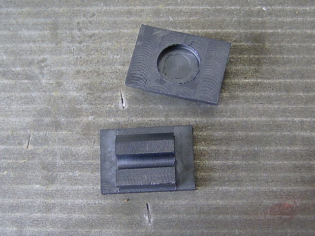
The buckles were simple milling jobs from brass bar drilled and reamed to take the valve spindles and then tapped to take the 7BA clamping screws. The valves themselves were machined square at the ends to fit into the buckles and the original slots in the valves milled out to a good fit on the valve spindles, free to move but with no play.
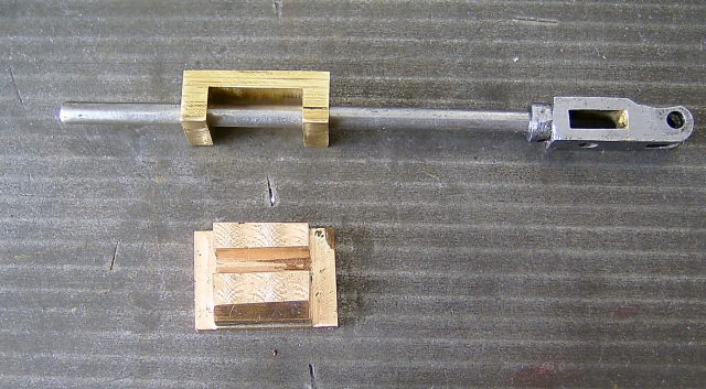
'U' shaped buckle to drive the valve
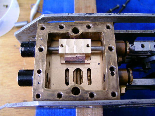
One valve assembled and fitted
I just need to find or make some suitable stainless clamping screws. I could really do with some stainless grub screws but I'm not sure if they are available in the size required.
I've mentioned before that the ends of the valves are not square to the ports and the ports open on one side before the other. As the valves were a little too long anyway, I thought I could get away with just truing the ends up. However, after doing this and checking the valve timing, it was apparent that the valves were now too short and the ports were opening much too soon in mid gear. Oh $&?!! I toyed with the idea of soldering a thin strip on each end of the valve and then machining them to the correct length but that would have been a bit of a bodge. Anyway, the valve cavities in the valves were a bit rough and I wanted to get rid of the exhaust clearance (or at least reduce it) so I decided to bite the bullet and make two new valves. Not a big job but one I didn't really want to have to do!
I'd got plenty of bits of gunmetal and bronze to make the new valves from but decided to try something I had wanted to do for some time now i.e. try using the PEEK material for slide valves. It had stood up well to superheated steam on Helen and the expansion would not cause any particular problem on a slide valve. It's also really nice stuff to machine!
I'd got a length of suitable sized bar and it didn't take long to machine up a couple of valves by milling in the vertical slide on the lathe, although it would have been just as easy to use the milling machine I suppose. It would have been even quicker if I hadn't had to break off the job to make a new bracket holding the silencer on the car. My brother had just called round to see me and we noticed the silencer was hanging off and nearly dragging on the ground!
I have just the exhaust cavities to machine up now and trim the valves to the correct length. I think I will do that in the mill as it's easier to see what you are doing when the work is flat on the milling table. It can be a bit awkward when stuff is mounted on the vertical slide.
New PEEK valves - just need the exhaust cavity milling to size