16/01/2009
Running on air!
I finished machining the exhaust cavities in the valves on the mill which was pretty straightforwad and then carefully trimmed the valves to length to give the correct lap. I had to fiddle a bit with the righthand valve as the ends of the valve were still not square to the ports even though the new valves had been made square. It turns out the ports themselves are slightly at an angle to the centreline of the cylinder block so the valve ends were machined at an angle to suit.
The valve faces were rubbed on some fine carborundum paper to get them nice and flat and then fitted into the valve chest. I then set the valves 'by eye' and bolted on the valve chest cover. The motion suddenly became very tight and investigation showed that one of the front fixing bolt holes in the steamchest broke through into the hole for the end of the valve rod! This was remedied by filing a flat on the end of the valve rod to clear the offending bolt. Actually, the ends of the valve rods need a flat filing on them where they go into the end of the steamchest anyway, otherwise you may get a hydraulic lock when oil gets into the holes.
After squirting a bit of oil into the steamchest I connected the inlet pipe up to my big aquarium airpump and after a bit of coaxing, the wheels went round, although fairly slowly and a bit jerkily. This improved after a bit and the chassis chuffed away quite happily. Out of interest I checked the air pressure from the pump and it was only 5psi so that was pretty good (The pump is designed to deliver large volumes of air at low pressure for supplying air stones in ponds etc.)
You can download a short, not very good qaulity, video of the chassis running here. Note that it's a big file and may take some time to download!
I feel a lot happier now that I know the chassis runs reasonably well and after a bit of fine adjustment on final assembly it will run ok (it's all really only lashed together at the moment). The maximum valve travel is a bit less than the theoretical due to lack of travel of the die blocks in the expansion links (the radius rods hit the top and bottom spacers on the links before full travel can be reached). The theoretical travel should be 0.340" but I can only get 0.300" at the moment. The lap on the valves is 0.077" (to suit the port spacings and the existing valve travel) and the lead is 0.010". With these figures, the maximum cut off in full gear is 80% so with the reduced valve travel it's probably between 70 and 75%. I can easily increase the available travel by filing a bit of clearance on the radius rods.
I am sure it would run much better and smoother on steam. The problem with running on air is that you don't get the expansion as you would with steam so once the ports close the air in the cylinder is not doing anything, in fact you can finish up with a partial vacuum in the cylinder towards the end of the piston stroke. I am sure this is why chassis tend to run a bit jerkily on air, one cylinder is trying to overcome a vacuum in the other part way through the cycle.
What to do now? I think the way to go now is to sort the coupling rods out, reassemble all the inside valve gear properly, fit the axle pumps, and then work on the outside cylinders and outside valve gear. There's not much to the outside valve gear though, just the rocker arms and connecting links to the outside valve spindles. I'm very tempted to then stick the boiler back on and give the chassis a steam test before starting any repainting.
23/01/09
I've been working on the coupling rods over the last few days and cleaning them up with needle files and sanding drums in the trusty Dremel. There were some quite bad scratches on the rods left from the initial filing but I've managed to remove all but the very deep ones. As expected, the holes for the leading and trailing bushes were quite a bit out of position and the bushes badly worn or had been deliberately made oversize so that the wheels would go round without binding! New bushes were made for the main crankpins from the bearing grade Peek and then the leading and trailing holes in the rods moved to line up correctly with the crankpins using an endmill to enlarge the existing holes. New Peek bushes were then made for these. The Peek bushes I fitted on Helen's coupling rods seem to be holding up well with no sign of any wear yet.
The rods were then fitted and after a little bit of easing of the leading and trailing bushes, the wheels rotated quite freely so the quartering must be reasonably accurate. I connected up the air pump again and after a bit of help the chassis ran steadily forwards but was a bit reluctant to go in reverse. Mind you, the air pressure was still only 5psi and I have only roughly set the valves.
I'm now looking at the outside cylinders and the rockers etc that drive the outside valves. There doesn't seem much wear in the pins connecting everything together so that's good news. The brackets holding the centre pivots for the rockers seem to need a bit of adjustment as the pivot pins are not quite midway between the inside and outside valve rods which means the valve travel on the outside valves is slightly different to the inside ones. It will just mean either milling a bit of the face of the bracket that bolts to the frames or fitting a shim, depending on which way the bracket has to be moved. Also, the LH bracket needs to be moved forward slightly as the rocker lever is not at right angles to the frames when the inside valve is in mid travel. I can do this by elongating the mounting holes slightly and moving it forward.
Another slight difference to the original design is that these rockers are dead straight whereas in the ME articles they are shown as cranked i.e. shaped like a boomerang. I believe the full size rockers were also cranked which had some effect on the valve timing to the outside cylinders.
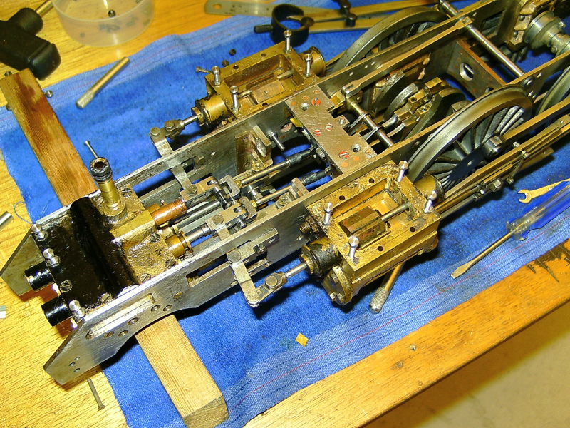
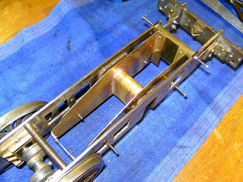
Outside cylinders and rocking levers etc fitted to check the fit etc.
The outside valves are driven the same way as the inside ones were i.e. by flats filed on the valve rod but the actual rods are threaded into the valve crossheads so some form of adjustment can be made by screwing the rod in and out. However, I think I may adopt the same method as I have done for the inside valves which allows more precise positioning of the valve.
As a matter of interest, Tony has sent me some photos of another Kingette chassis which another member of the 2½" Gauge Association took to the Rally at Little Hay last year. This appears to have the valve gear built as per the 'Words and Music' but it's difficult to see from the photos how the necessary clearances have been achieved. It doesn't look as though the crossheads and slidebars have been hacked about as Tony's have so there may be a way to get everything to fit! The radius rods are raised and lowered by the original suspension links but as the chassis has no boiler fitted you can't tell if the lifting arms will hit the boiler barrel (as I suspect they will).
13/02/09
3 weeks since the last update! I haven't been idle though and have been doing a bit to the King.
The brackets for the rocking levers proved to be quite a way out and both needed a thick shim under the bolting face to move the pivot further out from the chassis and equalise the valve travel so that both inside and outside valves moved the same distance. The shims were made from bits of steel sheet soft soldered to the brackets and then filed to shape and drilled for the mounting bolts.
One of the rocking levers appears quite different to the other so I wonder if it is not original? The hole for the pivot pin at the outer end of this lever was too far from the centre pivot by quite an appreciable amount so the hole was drilled out and a piece of steel bar loctited in to fill the old hole. A new pivot hole was then drilled through the bar in the correct position and the slot sawn out and filed to shape.
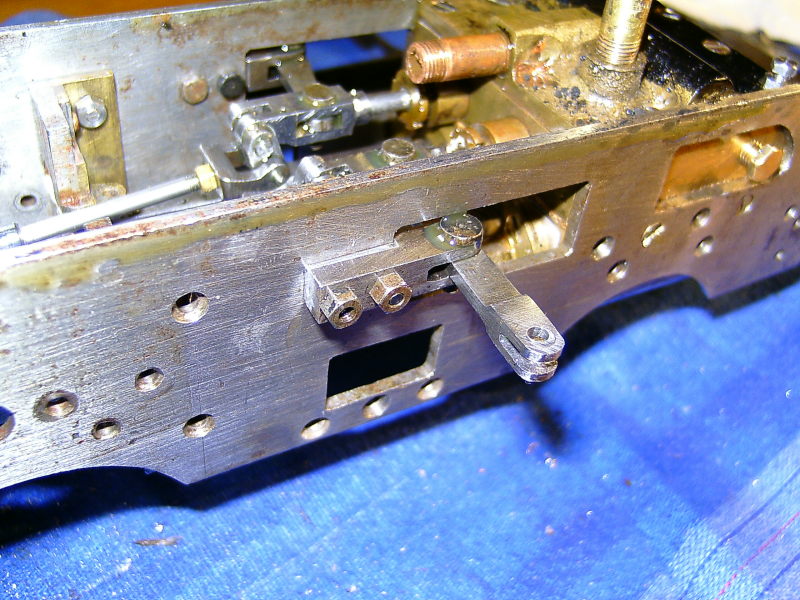
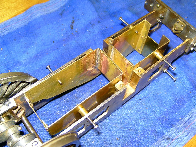
Rocker showing shim on bracket and repositioned outer pivot hole
The holes in the little links that connect the rockers to the outer valve spindles were worn oval so I drilled these out and fitted tiny bronze bushes to bring them back to size. Quite easy but a bit fiddly to make them!
I decided to change the method of driving the outside valves to the buckle method as done for the inside valves and the buckles etc were made exactly the same way. The valves themselves were ok and just needed machining to fit the buckles and shortening to give the correct valve lap. They were too long just as the original inside valves were.
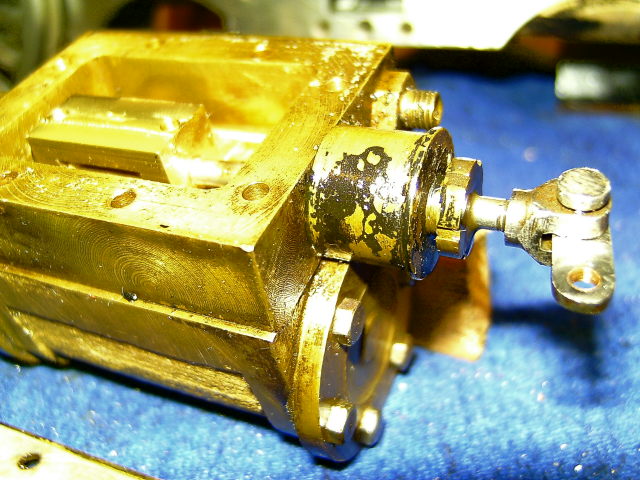
New valve buckle and link with bronze bush
I managed to find a supplier of small stainless steel hexagon socket grub screws and I'll use these to clamp the buckles to the valve rods for adjusting the timing. I ordered a bag of 50 but unfortunately they only sent a bag of 5! When I got in touch they promised to send the rest asap but that was 2 weeks ago and still no sign of them!
After all the above I temporarily fitted and connected up the outside cylinders and ran the chassis on air again. It runs but not quite as well as with just the inside cylinders. I think there's a bit more friction now with all 4 cylinders so it really needs a bit more pressure. It still runs on 5psi though so it's looking promising!
The outside cylinders still need new rings fitting and the port faces lapping but I'll do all that before the final assembly. At this stage I'm more interested in proving the valve gear is ok and that the chassis will run.
The chassis could now be stripped again and painted but before that I thought it best to check that everything else such as the boiler and running boards fit properly. I don't want to have to start altering things once the chassis is painted!
The boiler originally had a brass inner ashpan between the frames to try and keep ash away from the rear axle (as I had made for Helen) but this was quite a poor fit and I decided to make a new one. This was made from thin brass sheet shaped to fit snugly to the bottom of the firebox and to extend below the bottom edge of the frames. The removable ashpan will just be a shallow U which fits over the bottom of the inner ashpan and held in place with a pull out pin. Inside the inner ashpan I silver soldered a U shaped cover which fits over the rear axle and completely seals it from the ash etc. The old one just had open slots in the sides to clear the axle which allowed ash to get to the horns and the bearings.
The boiler originally sat on top of the inner ashpan and this seems to be the only way it was supported at the firebox end. I was not very keen on repeating this idea so I've fitted a square brass stretcher to the frames and the bottom of the backhead sits on top of this. I think the cab must have held the boiler on the frames as there are no brackets etc to do this. I think I will try and devise something a bit more secure!
Old inner ashpan
New inner ashpan
The original grate is very worse for wear so at the moment I am making a new one from 1/4"x1/16" mild steel strip. Helen's grate (made from the same material) seems to be holding up very well and I doubt if the Kingette will get anywhere as much use. I'm using the same design as for Helen with the rear flat section of the grate fixed and the front sloping part hinged so that it can drop down for dumping the fire.
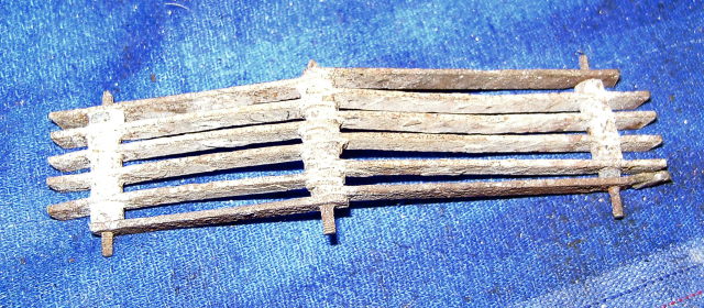
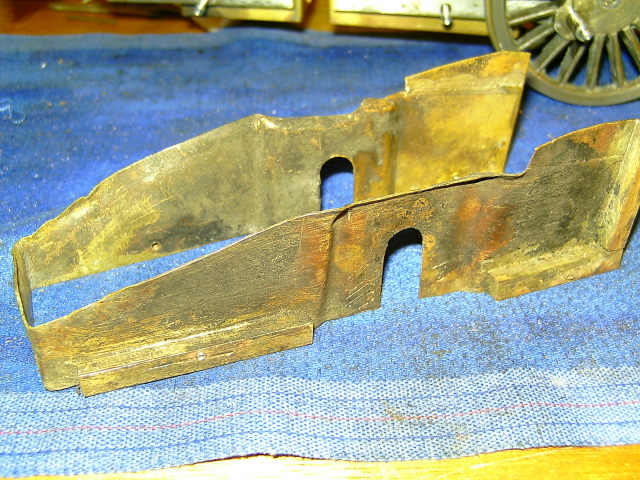
Old grate!
I think we're getting somewhere slowly!
20/02/09
I've now finished the new grate and also made the removable ashpan from some thin Zintec sheet I had lying around. The removable ashpan is held at the front by a couple of little hooks soldered to the front of the inner ashpan and by a pin at the back. At the front of the ashpan I've rivetted a piece of steel strip which sticks up and supports the hinged part of the grate when the ashpan is in position.
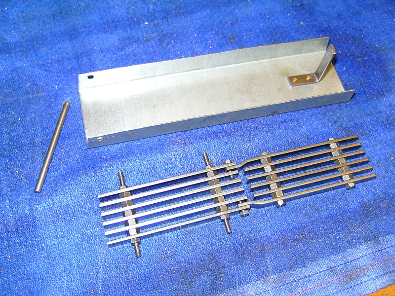
New grate and removable ashpan
Grate in position
I think it's now time to have a look at the plumbing for the axle pumps, hand pump, and injector. It will all have to be replaced I think as the original was a bit of a mess. The pipes to the boiler top feeds are a real problem. The originals were permanently soldered into the top fittings (an elbow which screws into a bush in the boiler) which means they have to be bent upwards to clear the firebox so that they can be screwed in and then bent down around the barrel to connect to the axle pumps and the injector feed. I might try fitting proper unions on the top feeds so the pipes can be connected after the fittings are screwed into the boiler. The original pipes are 3/16" diameter but I think I can go down to 5/32" if I use the thin wall tubing. This will look neater and enable smaller unions to be used. I used 5/32" pipe for the hand pump and axle pump feeds on Helen and it seems to handle the water flow ok.
Another problem is that there are 3 feeds (hand pump, axle pumps, and injector) but only 2 clacks on the boiler. I want to keep the injector feed completely separate so that leaves just one clack for the pumps. A common way around this is to connect the output of the hand pump to the inlet of the axle pump and then the output of the axle pump goes to the clack (in other words, the pumps are in series). This seems to work ok and has the advantage that only one water feed connection from the tender is needed instead of two. The big disadvantage ( to me anyway!) is that you have to close the axle pump bypass valve very time you want to use the hand pump! One thought I've had is to fit a separate clack valve for both pumps and just combine the outputs into the one top feed fitting. That way the handpump can be used as normal.
(I've just had a look at the original plumbing and the outputs of the hand pump and the axle pumps were teed together and fed through just the one clack. This still means that the bypass has to be closed to use the hand pump)
Running the pipes from the drag beam forwards will be a bit of a squeeze as they have to get past the ashpan and the axle springs but if I can use 5/32" pipes they should fit ok.
Another thing to look at is the lubricator. I would like to replace the monstrosity that was fitted with something more suitable and re-run the oil pipes so they are not so visible. There may be room to fit one under the cab floor and still have a decent sized tank. I think it best to stick with a twin ram pump with separate feeds to the inside and outside cylinders but this does make it more complicated. It would be nice to use a single pump and feed it into a common steam pipe before it splits to feed the inner and outer cylinders but I don't think that's possible without altering all the steam pipes.
05/03/09
Nothing much to report since the last update! I've had a look at the pipework required and it's going to be a bit of a squeeze to get all the pipes past the new ashpan. I can't do anything yet as I have had to order some pipe (from Doug Hewson) as I had run out of thin wall stuff. I compared a bit of 5/32" x 26swg pipe that I had with the original 3/16" thick wall on the loco and the bores are virtually the same.
I'm looking at the possibility of feeding a single oil supply into the dry header of the superheaters and just using a single ram oil pump. The original supply had two feeds, one fed into the side of the inside steam chest and the other split into two to feed into the outside steam chests. The pipe feeding the LH cylinder was much longer than that feeding the RH one. This is said to not be a good way of doing it as unless both pipes are exactly the same, one cylinder may get all the oil. Feeding the oil into the steam pipe before it splits to feed the cylinders ensures the oil is well mixed with the steam before it splits and all the cylinders should get an equal share.
Most of the last week or so has been taken up with a re-arrangement of the house. I've moved the office/study from the front upstairs bedroom into the back room downstairs. A lot of trouble moving all the stuff but a better arrangement. I can now use the front bedroom as a bedroom again! The small bedroom where I slept has now been fitted out with racking and shelving to provide more much needed storage space for tools and bits of locos, castings, etc.