30/03/09
I'm still waiting arrival of the copper pipe so I had a look at the two axle pumps in the meantime. The ball valves leaked,as expected, but cleaning the seats and reseating the balls sorted that out. A trial assembly with the eccentric rods showed that the rams were much too short. Also the pumps had been made to the 'old' design where the bore of the pump connects to the valve box through a small hole which can lead to air being trapped and ruining the pumping action. This type should have a narrow 'pin' on the end of the ram that goes through the connecting hole between the bore and the valve box and pushes out any trapped air. The old rams did not have this and because they were too short, it would have been easy for air to get trapped.
I decided to make a couple of new rams from stainless (the originals were brass or bronze) of the correct length and also with the pin on the end. These were a simple turning job with the slot for the eccentric rod cut with a slitting saw. I also decided to try replacing the old graphite yarn packing with a PTFE bush to try it out. The bush has a conical end to match the internal chamfer on the end of the pump body so that tightening the gland nut squeezes the PTFE tighter onto the ram to give a good seal (I hope!)
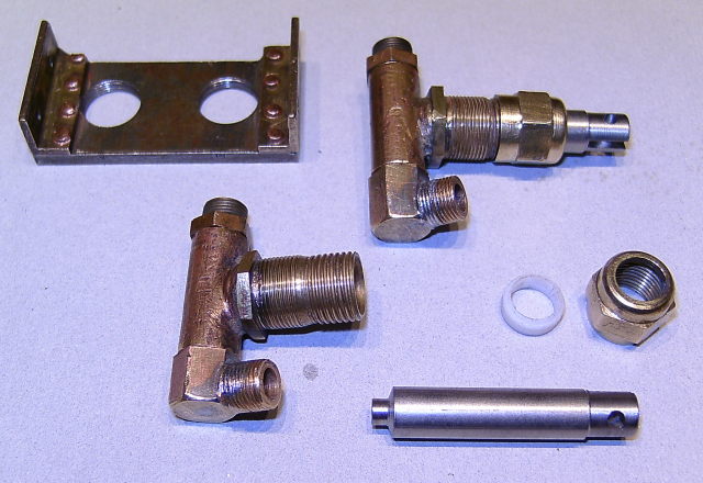
Axle pumps with new rams and PTFE packing
I've had another look at the plumbing and decided to simplify the tender connections by feeding the tender hand pump through the axle pumps. This gets rid of one pipe to the tender. In use, the hand pump feeds through the axle pumps into the same clack and the axle pumps draw water through the hand pump instead of directly from the tender tank. This does mean that the bypass valve has to be shut to use the hand pump but quite a few people seem to use this system for 2½" locos. In any case, the way the plumbing was done before, this had to be done anyway. The feed from the axle pumps to the bypass valve can be 1/8" pipe I think without causing any problems with flow. On Helen, the handpump feed and the axle pump feed pipes to the boiler clacks are both 1/8" and this doesn't seem to have caused any problems.
03/04/09
The copper pipe is on it's way so I'll be able to sort the plumbing next week hopefully.
In the meantime, I've had a look at the running boards and checked them for fit. The main running boards with the splashers are just held with a couple of bits of angle fastened to the frame with just one screw so I think I'll add an extra screw to each to stop the angles moving. Actually, the holes in the brackets are a bit out so I may make new ones. The top of the running boards should be flush with the top of the frames but they are not quite level towards the cab end. The curved front section is not fastened to the long bit at all and is only fastened to the front buffer beam by one screw. I'll fasten a piece of brass angle where they meet which will make the whole lot much stronger.
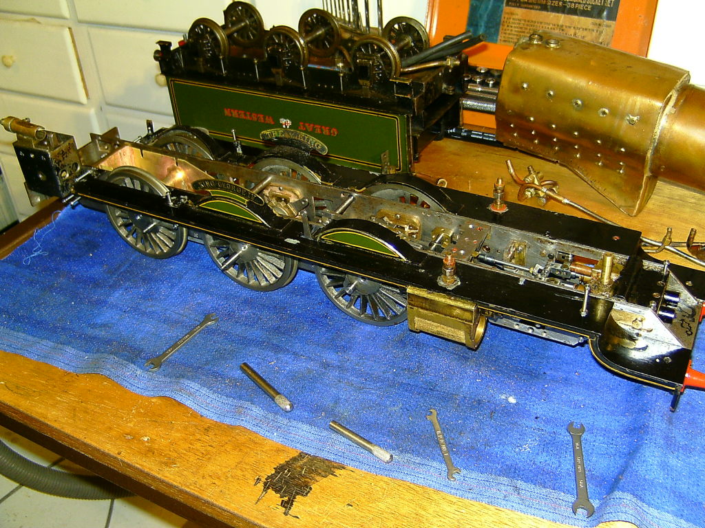
Running boards fitted to check the fit
The steam pipes to the outside cylinders screw into the top of the steam chests and go through a hole in the running boards. I think a spacer is needed between the top of the steam chest and the running board to stop the steam pipe pulling the running board down. One of the running boards was badly bent over the steam chest where it had been distorted by tightening the steam pipe.
If you look closely at the above photo you can see that the name plates are actually double sided. The 'inside' name is 'The Viking' but I don't think this was an actual name for any of the Kings. These plates were probably commercially made and could hold a clue to the actual date the loco was built?
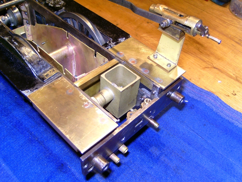
I temporarily fitted the lubricator/reverser stand to see what could be done to improve this. My thoughts at the moment are to fit a new lubricator between the rear of the frames underneath the cab floor. There's enough room to do this and fit a decent sized tank. The reverser can then be fitted to a simple plate to fasten it to the frames.
I may try a single ram lubricator of the Jim Ewins type and feed the output to the front end via a single 1/8" pipe. At the cylinders this would be split into 3 equal pipes to feed the inside steam chest and the two outside ones. I think so long as all the pipes are the same length all the cylinders will get a fair share of the oil. This would be the simplest way to do it. I'll fit a single check valve just before the pipes split.
The operating arm for the lubricator will be in the same position as the original so the same drive can be used. The only problem is the ashpan getting in the way again! I could actually fit the lubricator that I bought from Steam Fittings some time ago but I'd really like to fit one with a bigger tank if possible. The Jim Ewins type with roller clutches is very simple to make anyway so it won't take long to knock one up.
14/04/09
The copper pipe's arrived so I've made a start on the plumbing. The first job was to make a new bypass valve which could be fastened directly to the rear drag beam instead of the flimsy bracket used before. This carries the pipe connection for the rubber hose back to the tender. It's a simple screw down valve the same as the original but I've used PTFE to make the packing for the valve stem. There's very little pressure on the stem as it's in the return side of the bypass.
The original screwed connection for the tender hand pump and the injector water feed were just hanging in mid air with no real support so I took a leaf out of Curly's book and made a proper bracket for them fastened to the drag beam. The fittings are silver soldered to the bracket and the pipes will be silver soldered into the fittings making a good solid job.
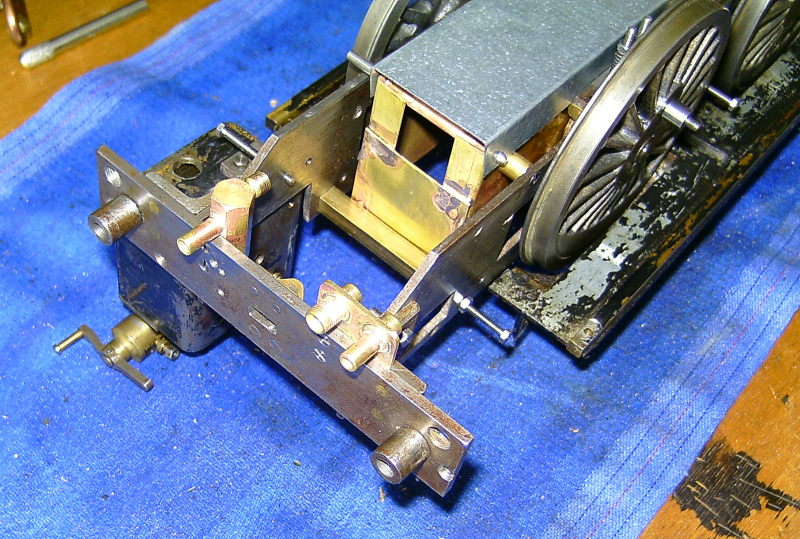
New bypass valve and pipe connections
The pipe to the axle pumps has to be split into two at the pumps and I made a manifold from brass rod drilled out, the open end plugged and the whole lot silver soldered up. The pipe route is a bit tortuous as the pipe has to have a joggle in it to go between the axlebox springs and the wheel. Unfortunately, there is not enough room for the pipe to go next to the ashpan. If I had thought about this earlier I could have made the ashpan a bit narrower to give more room. Too late now!
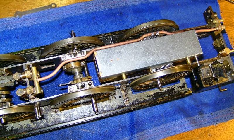
Water pipe to the axle pumps
Next I looked at the pipes for the top feeds. As mentioned earlier, these were originally soldered directly to the top feed fittings which makes screwing the fittings in a devil of a job. The pipe has to be bent up to clear the boiler so the fitting can be screwed in and then bent back down again around the boiler. Not very good really. I decided to attach the feed pipes with a proper nutted connection so that the pipes can be attached after the fitting is screwed in. The connections will look a bit out of place maybe but make life much easier.
The original pipes were silver soldered into the fittings but I managed to remove them by heating everything up and twisting the pipes out. As it happens, the top fittings are also a fabrication from two parts but fortunately didn't fall to bits when I heated them up!
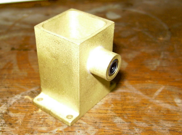
A bit of thought showed that if I could fit the boiler clacks into the actual top fittings this would make the plumbing a lot easier. The original clacks are separate and fitted between the frames so are a devil of a job to get at if they go wrong. Also, the feed pipe from the injector could run over the top of the rear wheel splashers as per the full size engine. This would be much easier than running it under the frames past the ashpan like the axle pump feed. The problem though is how to fit a clack into the small space available in the top fitting. Because the clack will be 'upside down' with the seating at the top, the ball will need a spring to push it up against the seating until you get pressure in the boiler. I'm not sure if there is enough depth in the boiler bush to get a long enough spring in there. The bush actually has a seating in the bottom which has a bit of bent copper pipe soldered in to direct the incoming water to the front of the boiler. It may be possible to drill this seating a bit deeper to give more room for a spring but I'll have to check first. It's a bit difficult to see inside the boiler to see how long the bushes actually are.
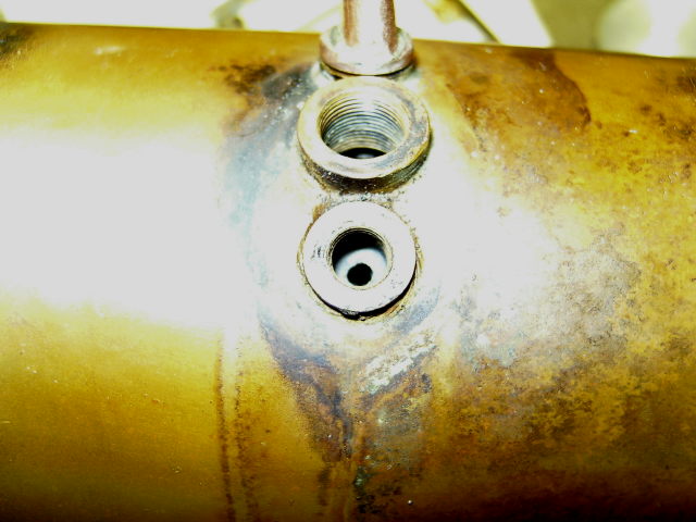
View of one top feed bush with seat at bottom
Another possibility is to use a poppet valve with an O ring instead of a ball but this would still need a spring under it to keep it seated. I did wonder whether a 'Goodall'(sp) type valve could be used. This consists of a hollow stem with a hole in the side with a piece of silicon tubing over the stem to act as the valve. The pressure in the boiler seals the silicon against the hole in the stem under normal conditions but opens up when water is forced in through the stem. Very simple and probably very reliable. It's used a lot on garden railway type locos for filling the boilers under steam from a pressure bottle and also as a filler valve in the gas tanks. I'm sure I read recently that the Goodall valve had been used successfully as clack valves in larger scale models? I can see it working with a high pressure feed from an axle pump or hand pump but I wonder if it would work with an injector feed?
24/04/09
After much deliberation I've decided to make new top feeds with a recess in the threaded part to house a ball for the clack. This means there will be room for a small spring under the ball to hold it on it's seat until the boiler gets up to pressure. These didn't take long to make from bronze bar. The top of the fittings were milled roughly to shape and then finished by filing. A threaded stub was then soldered in to form the feed pipe connection. I just need to make a couple of light springs from bronze or stainless wire and they are done.
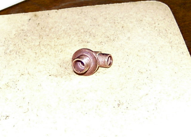
New top feed fitting showing recess to take the ball
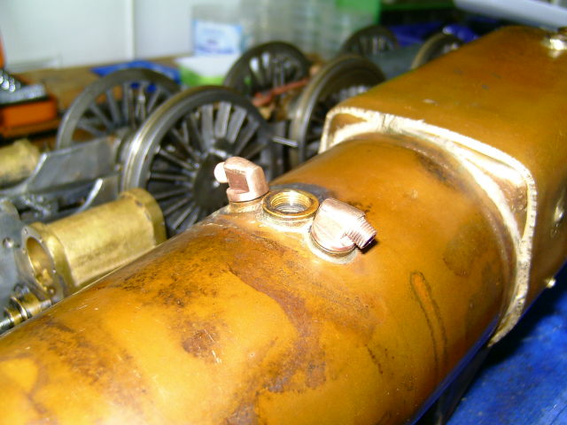
Both fittings on boiler
Next job was the feed pipes from the axle pumps. I made another manifold from brass bar to connect the feeds from the pumps together and a Tee piece to connect the pipes to the boiler top feed and the bypass valve.
Pump outlet manifold and Tee piece for bypass pipe.
That just leaves the pipework for the injector to do. This will be run over the wheel splashers as per the full size job so can be done later.
My thoughts turned to the lubricator next. I had intended to make a new one from scratch but instead decided to modify and fit the one I had bought from SteamFittings some time ago. I may as well use it for something! This is of the Jim Ewins type fitted with roller clutches and the output can be adjusted by changing the thickness of the spacer between the O rings in the pump barrel. The output may be a bit high for a 2½" gauge loco but we'll see when the loco is run again.
The only mod required was to cut off the mounting lugs on the bottom of the tank as they took up a lot of room. They would not be needed anyway as I intended to bolt the tank to the inside of the frames under the cab floor. I also reduced the height of the tank a little by machining about 3/32" off the base. This was very thick (the tank is a casting) and was originally about 3/16" thick.
Lubricator body before removing the mounting lugs
The tank now fits nicely in the space allocated and will be hardly noticeable, unlike the old one which took up half the cab!
Lubricator tank mounted between the frames
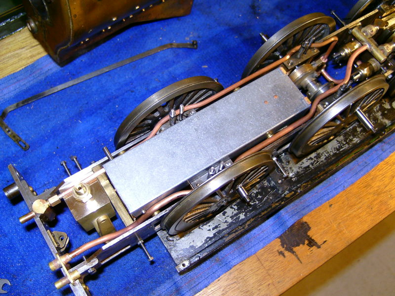
Underneath view also showing the pipe to the bypass valve
The drive for the lubricator will be taken from one of the pump eccentrics as before but not the same one so I will have to solder a lug onto the other eccentric strap for the operating rod.
I'll probably modify the oil pipe connection from the outlet of the lubricator. At the moment it is a straight fitting and if I connect the oil pipe to this with a bend, the pipe will finish up rather low down and close to the track. Alex Ellin used one of these lubricators on his 2½" Horwich Crab and he replaced the straight fitting with an elbow one which means the oil pipe connects to the side of the fitting rather than the bottom. I'll do the same I think.
24/01/2010
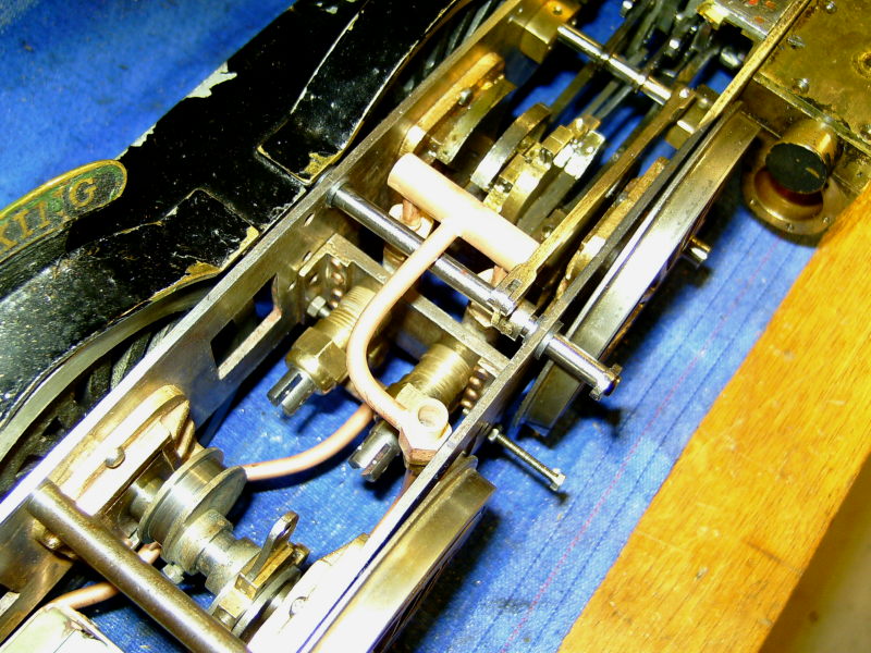
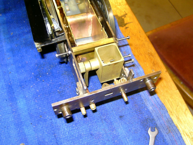
I've decided it really is time I got cracking on this job again and I've been doing a bit over the Xmas period. I've fitted extentions to the running boards on either side of the cab and made a new stand for the screw reverser to replace the old lubricator tank.
Running board extensions and reverser stand
When the cab is refitted, the floor will cover the gap between the frames and allow access for filling the lubricator.
Over the last couple of weeks I've been carrying out some detective work and I am certain I have now traced the original builder of the Kingette and it appears this loco has had some very distinguished owners over the years!
Tony and I have been trying to find out the history of the Kingette for some time now but with very little luck until now. A few weeks ago Gerald Chandler sent me a copy of an email he had received from Clive Young, a fellow member of the 2½" Gauge Association. Clive had been searching for an article in Engineering in Miniature and had come across a report of a 2½" Gauge Rally in 1988. This report carried a photo of the Kingette along with a potted history including names of the owners past and present. At last, something concrete to work from!
According to the article in EIM, the loco was built in 1936 by an unknown builder. It was then purchased by Noel Van Raalte aka Bro. Wholesale (those who read the old LBSC articles in ME will recognise the names) on the recomendation of LBSC himself. The loco then passed onto Tom Glazebrook aka Inspector Meticulous who later sold it to George Barlow of the Romney Marsh MES. George sold it to Wilfred Hills of the same club (who owned it at the time the article was written) and on Wilf's death the loco passed onto Cyril Carter. Friend Tony then purchased the loco from Cyril Carter's estate following his death.
The article also says that the loco still had it's original boiler at this time (1988) so the new one must have been fitted later. The serial number on the new boiler suggests to me that it may have been built in 1994 which would fit in with the above information.
Anyway, seeing this article spurred me on and I spent many hours looking through old LBSC articles in Model Engineer to see if I could find any mention of the loco.
The first reference I found was in ME for June 6th 1940. LBSC wrote a sort of obituary for Noel Van Raalte following his death and mentions how they first met and later became close friends. According to this article, Noel had bought the Kingette before he even knew LBSC (which contradicts the EIM article) and contacted LBSC to see if he could carry out some repair work on the loco. LBSC invited Noel to bring the loco to his home at Purley so he could have a look at it. Upon seeing it, LBSC decided he could not carry out the work required in the time available and recommended Noel took the loco to a Mr Frank Baldwin instead.
I then found another reference in ME for October 21st 1937. In this, LBSC relates the story of a Kingette built by Mr T G Marchant which after several years hard use passed on to a new owner. The new owner had commissioned Mr Frank Baldwin to overhaul the loco which he had done so. Mr Baldwin then brought the loco to LBSC's house for a test run on the Polar Route in the prescence of the new owner. The loco was given a run by LBSC himself who said she 'responded well' and then by the new owner and his friend. The new owner is not actually named but I have no doubt that it was Noel Van Raalte.
I recognised the name of Mr Marchant and looking back through the Kingette series in ME, came across a photo of the part built frames and front bogie frames of Mr Marchants loco (ME for September 15th 1932). Comparing the photo, although poor quality, to 'our' Kingette frames, I am positive they are the same. There are several distinguishing features which are identical on the frames in the photo and the frames I have before me. It is mentioned that Mr Marchant had made his own cylinder patterns and had the cylinders cast and I would say that the cylinders on 'our' Kingette are probably not commercial items. There are no markings such as Bonds or Kennions which appeared on their castings.
Mr Marchant wrote several letters in ME at the time and one that appears in February 1934 mentions that he was busy finishing off the Kingette he was building. Apparently he ran a small model engineering company at the time.
So, I am convinced that the loco I'm rebuilding is the one originally built by Mr Marchant and which passed through such distinguished hands on route to friend Tony. I have continued looking back through ME's but cannot find any further photos. I was expecting to find a photo of the loco running on Noel's 'Giant Racer' circuit at Burlesdon but, although the Kingette is mentioned several times, no photo appears. There are photos of Noel's other locos, Tishy and Annabel the Mallet however. Strange. It makes you wonder if he was not particularly keen on this loco which was why he passed it on to Tom Glazebrook (a close friend).
The fact that the loco obviously did run on the Polar Route gives a bit more credence to the possibility that this is the Kingette being driven by Cyril Grose in Brian Hollinsworth'g book on LBSC. If only I could find a copy of the original photograph! It might be then possible to read the nameplate on the loco.