SIMPLY LONGER
6
05/12/09
Not much done over the last month! I've been busy with other things such as machining the driving wheels for my brother's S15.
I've made up the spring plates that go over the ends of the spring pins. These were a simple job from 1/16" x 3/8" mild steel strip. One was marked out and drilled and then used as a jig to drill the rest. Finally, the ends were filed round using my usual silver steel filing buttons.
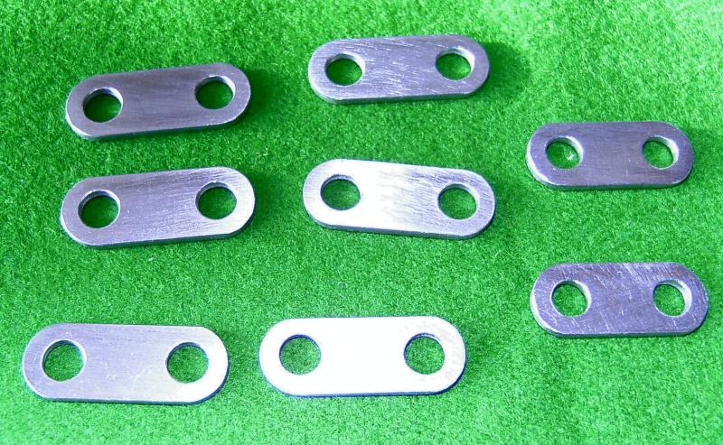
Spring plates
The next little job was to make up some brackets to support the running boards along their length. I'll be fixing some angles to the top of the motion brackets to fix the running boards to the top of these but there are large gaps inbetween those and the buffer beams.
On Helen I used plain bits of angle bolted to the frames but for 'Simply' I decided to make up some proper brackets where they will be seen. These were fabrications utilising a length of 1/4" x 1/16" steel strip bent at right angles and silver soldered to a triangular piece of 1/16" steel sheet. The rough brackets were then cleaned up, milled on the edges to true them up and drilled for the bolts to fasten them to the frames. Two of the brackets which fit just behind the cylinders are just bits of angle as space is a bit tight here.
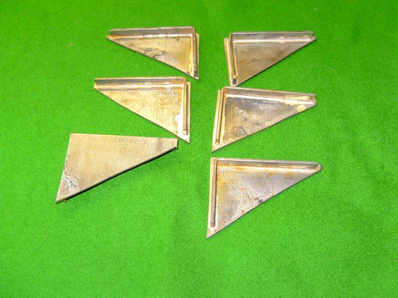
Rough brackets after soldering
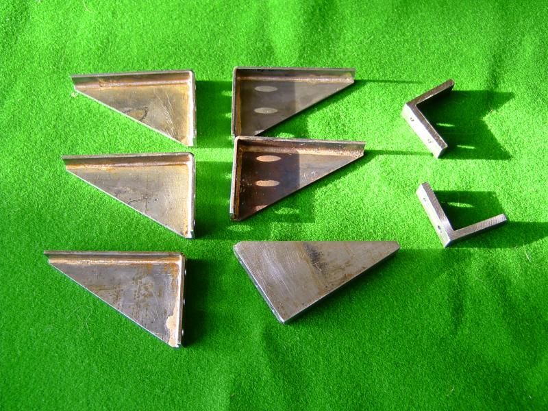
Finished brackets after machining
You may have noticed that I'm finding other little jobs to do rather than start on the coupling rods! Actually, I want to get all the holes drilled in the frames so that I can get those finished and painted. Wth this in mind I've been trying to work out which holes still need to be drilled. I've decided to fit brakes to the driving and trailing axles (there is not room to fit them on the leading axle - the hangers would foul the rear cylinder covers) so I've had to draw out all the operating gear for that. This requires holes for the brake hangers and brackets for the brake column and operating shaft etc.
I've also drilled a couple of holes in the rear of the frames so that the injector feeds and water supply can pass through the frames rather than have to go underneath.
I suppose I will need some sort of operating gear for cylinder drain cocks which will need mounting holes as well !
Inbetween all this I've been working on the design for the balanced slide valves and I think I've finally arrived at a design I can live with and won't be too difficult to machine. The exhaust will pass through the valve and out of the top of the steam chest and enter the smokebox through the side of the saddle. I'm also working on the design for a Lempor type exhaust which will fit nicely into the space available and using the tall chimney of the Simplex. One day I will build something straight from a set of plans without having to design everything as I go along!
At the moment I'm working on filling in all the 'spare' holes and screw heads in the frames of which there are quite a few! Once that's done the frames can be painted and wheels etc. fitted once and for all (hopefully!).
24/01/2010
Well, another year's gone by! I don't seem to have done much over the last month or so as I've been bitting and bobbing with various other jobs.
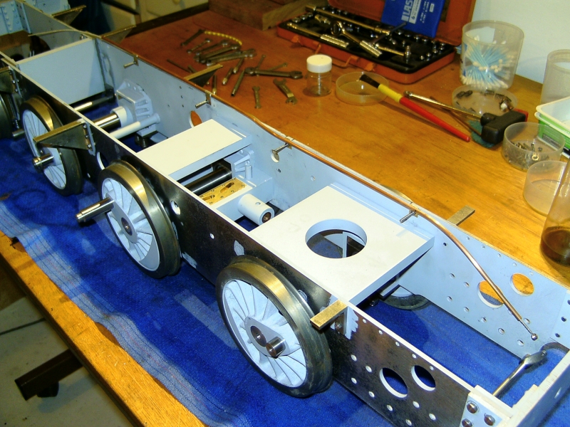
I have done a few bits on Simply though since the last update. The running board brackets have been fitted and the brakeshaft made and fitted. This runs in PEEK bearings on 2 little brackets bolted to the bottom of the frames just behind where the ashpan will be.
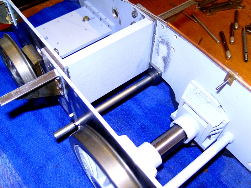
Brakeshaft made and fitted with 2 brackets
I've also worked out the operating gear for the cylinder drain cocks. There is just room at the bottom of the frames in front of the cylinders to squeeze in a couple of bushes to take a cross shaft to operate the cocks. Rather than a complicated linkage from the operating lever in the cab to the shaft, I'm using a bowden cable running in a length of 1/8" diameter copper tube. The cable will be an old bottom E string off a guitar (I've got plenty of those!) which has a nice brass ferrule already fitted to connect it to the operating arm on the cross shaft.
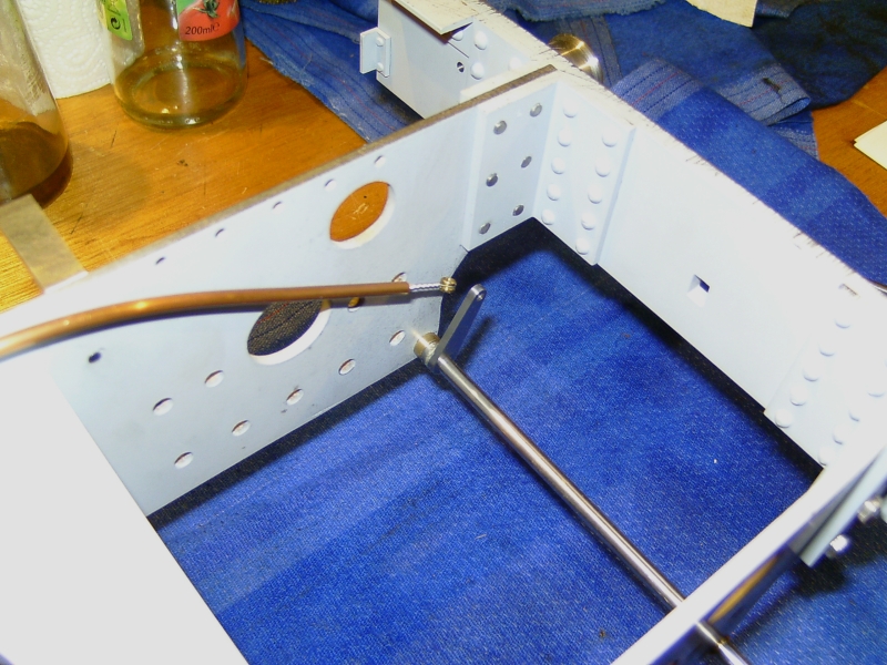
Cross shaft for operating drain cocks
Copper tube containing bowden cable
The cylinder drain cocks will be the sort designed by Don Young which use a spring loaded ball rather than a taper plug.
I had a look at the cylinders before Xmas and measured them up to check the machining that had already been carried out when I got them. The bores are spot on size and seem to be parallel but the finish is very poor. Rather than try reboring them slightly larger I'm going to get one of the expanding cylinder hones and see if I can clean the bores up with that. They should only need a few thou taking off.
One thing I did find wrong was that the bores are the wrong distance from the port face. One is 0.020" too high and the other is 0.020" too low! This makes a difference between the two of 0.040" which is too much to ignore so I'm going to have to machine 0.040" from one port face to make the two blocks the same. Bit of a pain but leaving them as they are would mean the distance between the cylinder centreline and the valve spindle would be different for the two sides leading to other complications.
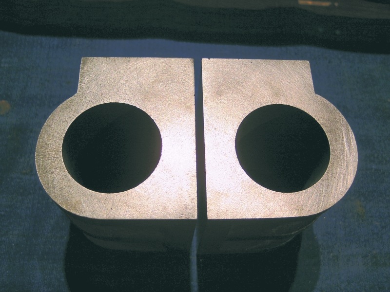
Cylinder castings - You can see the difference in the bore positions!
Anyway, I'm going back to the Kingette for a bit as I really should get that finished, so for the time being updates here will be few and far between!
21/07/12
Wow! Is it really 2 ½ years since I did anything on this project!
I haven't done any more construction work but have been looking at the boiler again. I've decided that the design I came up with in the beginning doesn't have enough tube area for the enlarged grate area. The tube area is only about 10% which I don't think is enough so I'm now looking at either increasing the number of tubes or increasing the diameter to give at least 13% to improve the 'breathing'. Both methods are difficult with the existing boiler design and I may have to change to a Belpaire design rather than a round top so that I can increase the size of the firebox tubeplate and have sufficient gap between the firebox wrapper and the firebox outer shell to give adequate water circulation.
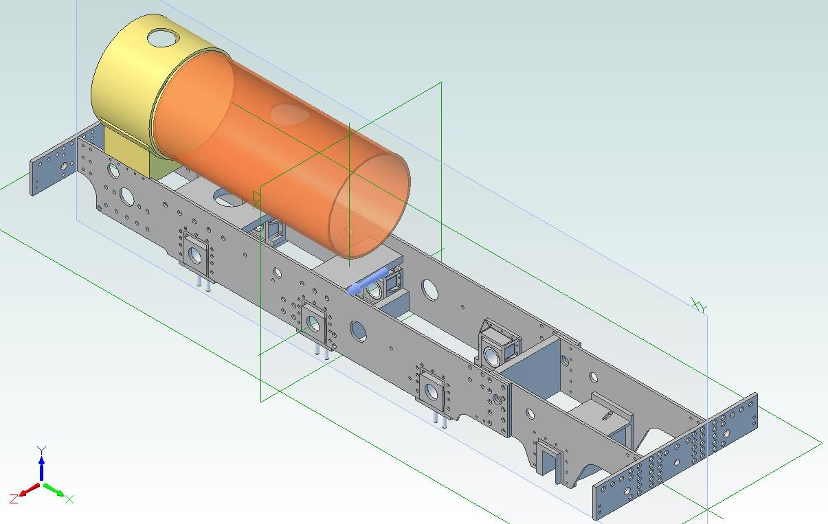
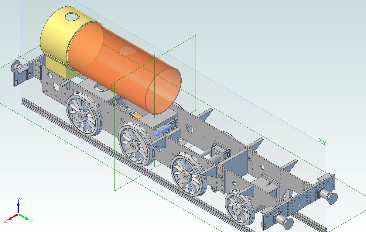
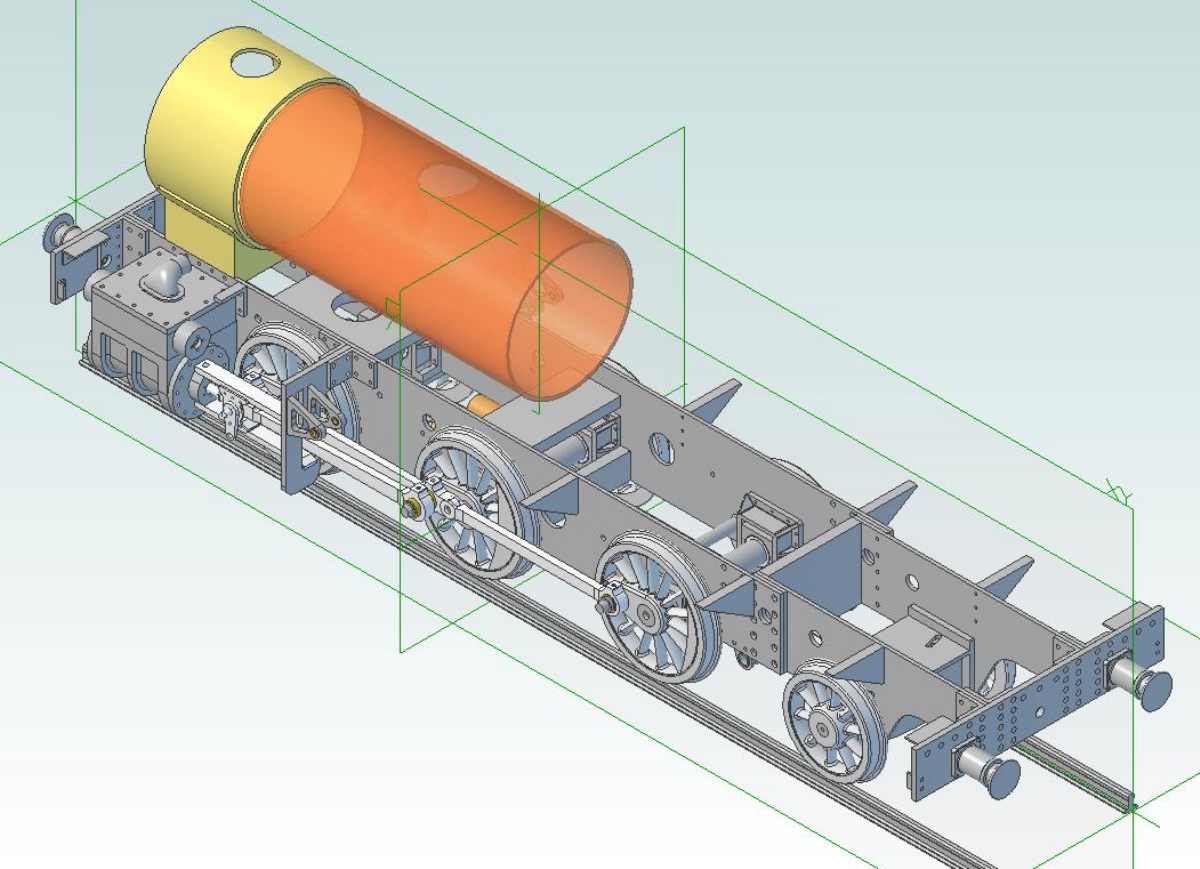
I've also started drawing out the loco in 3D CAD and have already found several mistakes on my original 2D drawings!
01/08/2012
I had a bit of a play today with the balanced slide valves. The exhaust will exit through the top of the valve and out of the top of the steam chest via a cast or fabricated fiting. The valve is fitted with a hollow balance piston which seals againgst the underside of the steam chest cover and reduces the area of the valve exposed to steam pressure, thus reducing the force pressing the valve onto the port face. The exit 'hole' in the steam chest cover is elongated so that it does not obstruct the flow of exhaust steam when the valve is at the end of it's travel.
The exhaust pipes enter the smokebox through the sides of the saddle and sweep upwards to where they are joined. A baffle, or Kordina, will be fitted at the join to keep the two exhaust streams separate until they reach the blast nozzle/s. The Kordina prevents the two exhaust streams interfering and also helps to induce a vacuum in the two exhaust pipes, reducing any back pressure even further.
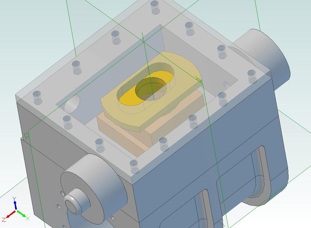
Balanced Slide Valve Arrangement
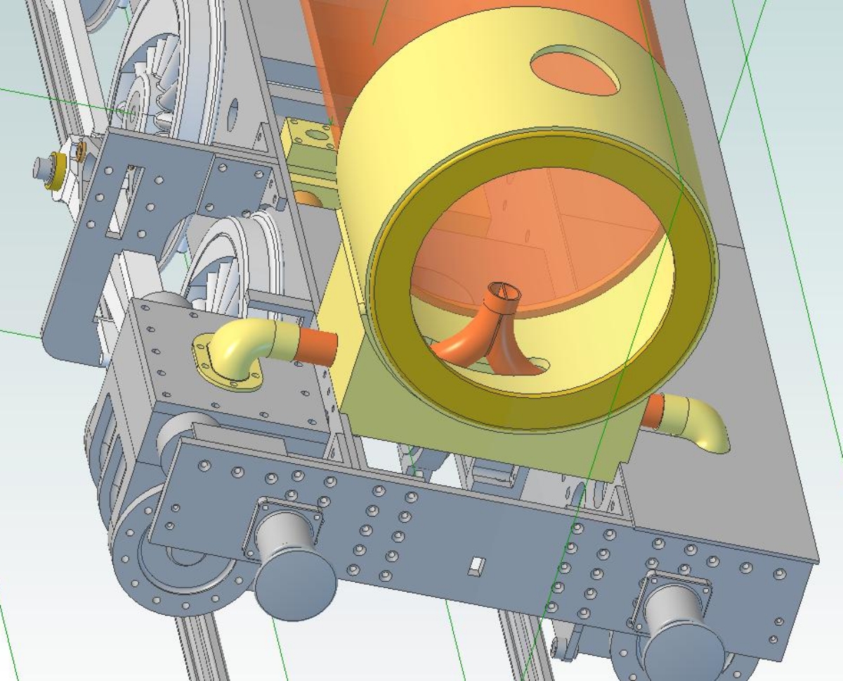
Exhaust Layout
08/08/2012
I've been playing about with the boiler design and it's heading towards a Belpaire firebox with a partly tapered barrel. A bit more complicated to make but maybe the only way to get sufficient tube area to match the grate and still have sufficient water space around the firebox. The latest boiler design has twenty one 7/16" firetubes and four 3/4" superheater flues giving a tube area of about 14% of the grate area.
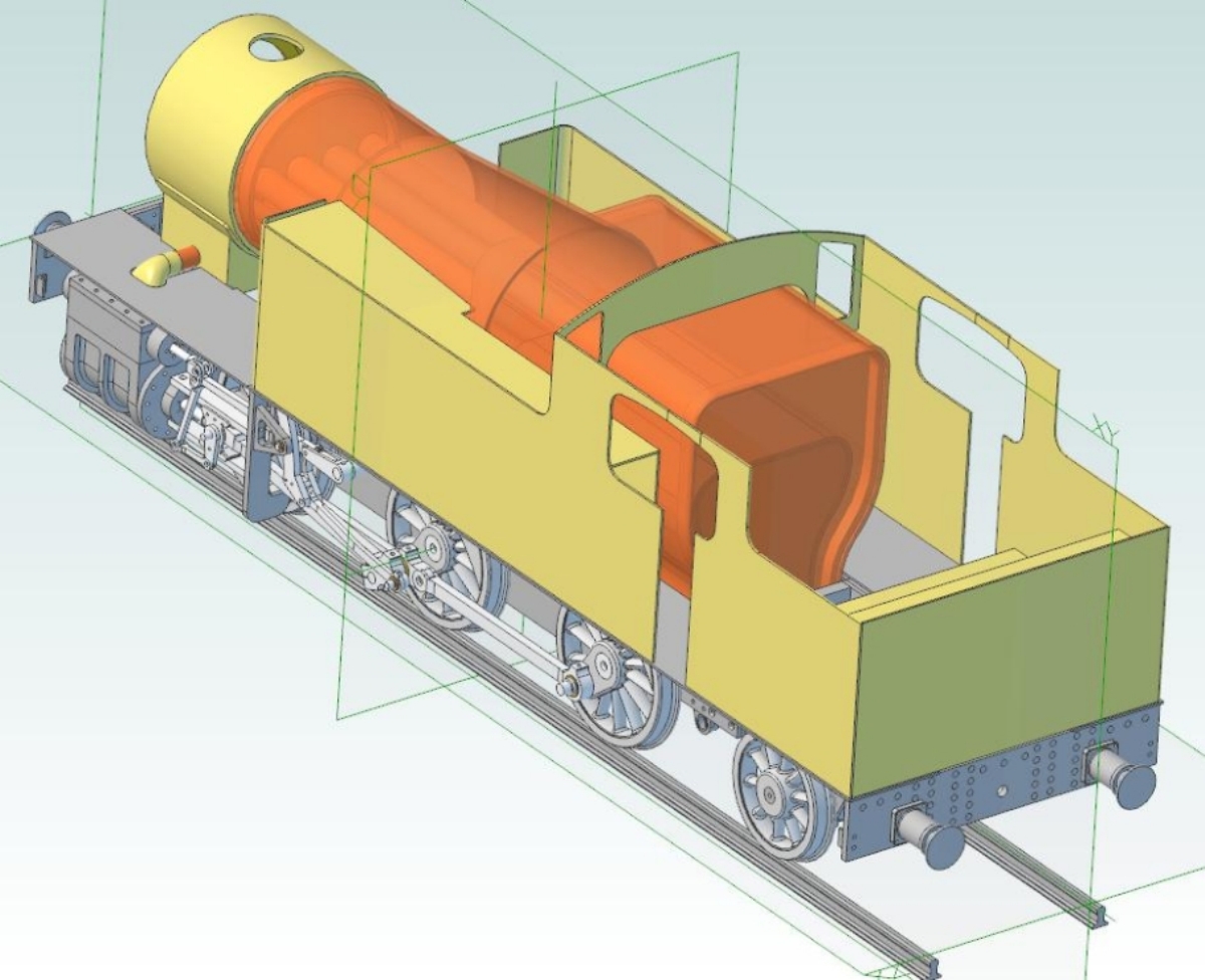
The latest boiler incarnation
Previous Page