LBSC Green Arrow
4
23/10/2020
Wow, it's nearly five months since I last did anything on Green Arrow! I've been busy with other things and the time just seems to have flown by. Not being able to live a normal life due to this cursed virus thing doesn't help matters. We did manage to sneak in a 2½" gauge Rally at Rugby in September just before the 'Rule of Six' came into force and everyone enjoyed the break from the isolation. It was good to see people again and have a run with a loco.
Anyway, I managed a couple of hours in the workshop tonight and carried on with the cylinders.
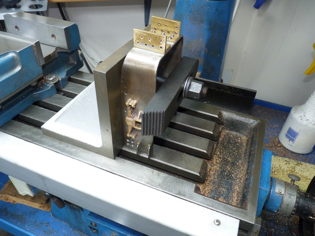
When I left off last time I had remachined the rear cylinder covers so the next job was to drill the cylinders for the fixing bolts. As the cylinder covers had already been drilled I had to use them as the template by clamping them onto the cylinder with a long bolt through the middle and suitable washers.
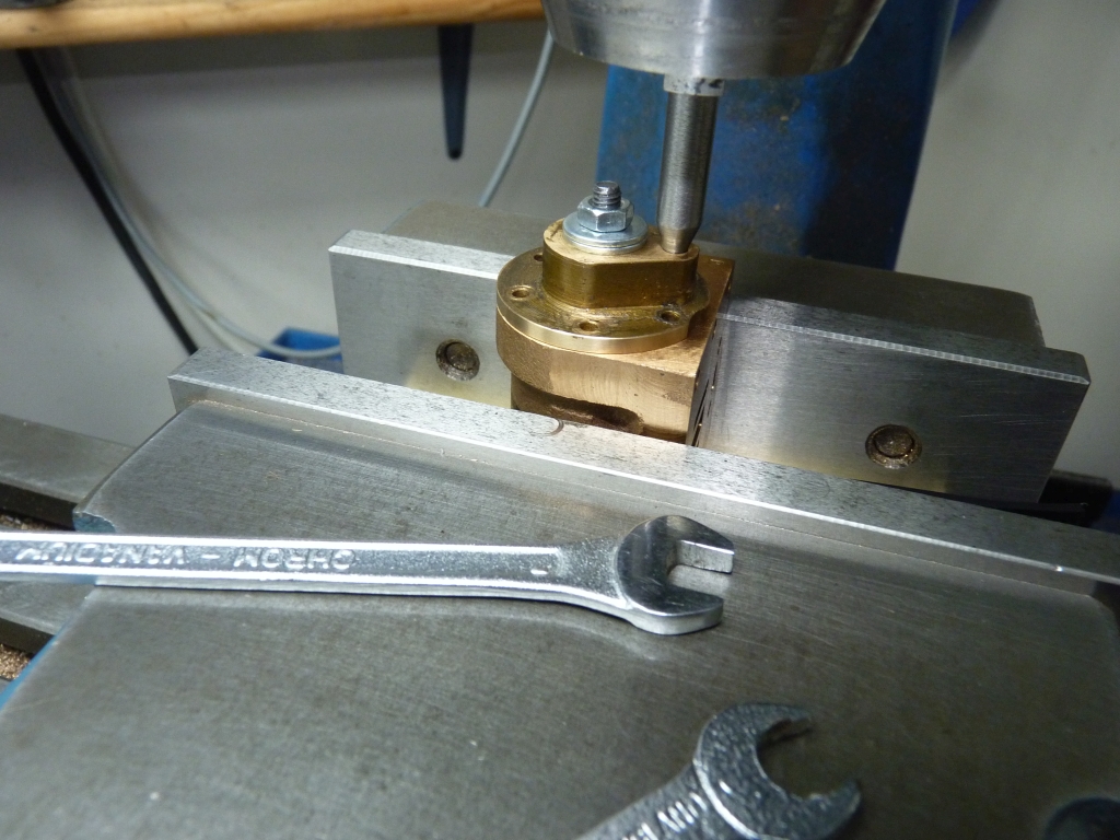
To ensure the hole for the slidebar was truly vertical to the piston rod I first lined the mill spindle up with the cylinder bore using a DTI in the chuck without the cylinder cover in place . The cover was then held in place with the bolt and a pointed centre held in the chuck. The table was then moved in the X axis only and the cover's position adjusted until the end of the pointer lined up with the slidebar hole. It was then in the correct place. The bolt was tightened to clamp the cover firmly in place and all the holes for the cover bolts drilled and tapped using the cover as the drilling guide.
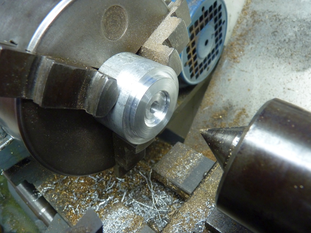
I then moved onto the front covers. These were a bit rough and, as for the rear covers, the spigot that fits the cylinder bore needed a few thou taking off. The front covers are not as critical as the rear ones so to reduce the diameter of the spigot and take a skim off the bolting face I just held them by the edge in the 3 Jaw chuck and used the end of the tailstock drill chuck to square them up.
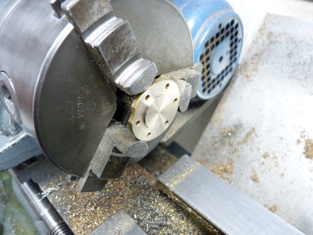
This 3 Jaw chuck is the original Burnerd that came with the lathe when I bought it and it's still pretty accurate despite it's age. Plenty accurate enough for this job anyway.
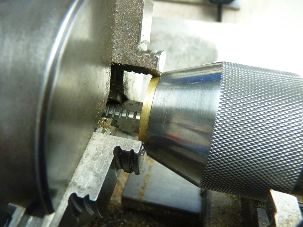
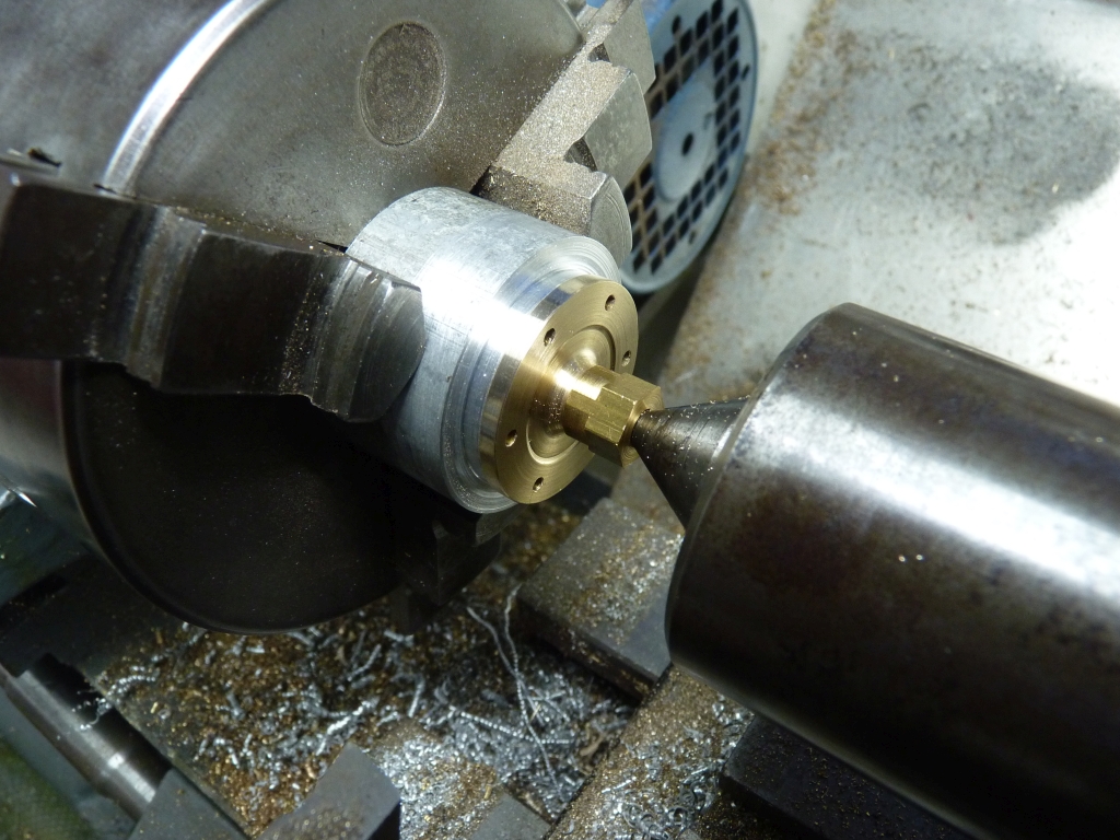
The process was repeated on the front faces of the covers but this time the cover was squared up by pressing it against a spacer on the face of the chuck. That would ensure that the front face would end up reasonably parallel to the previously machined bolting face.
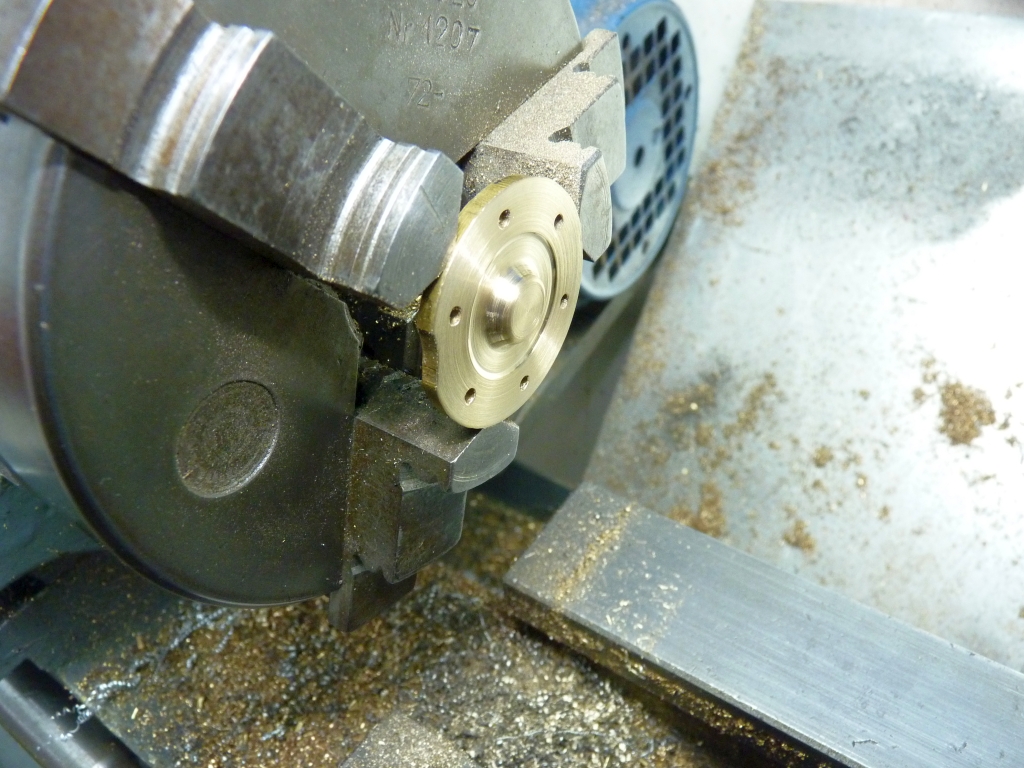
Whilst I had the cover held like this I also cleaned up the spigot and the recess on the front face.
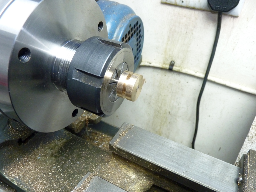
Last job was to clean up the outside edges of the covers. There wasn't any way to chuck the cover so that I could machine the outside edge so I did it by turning a bit of aluminium bar with a recess in the front to take the spigot of the cover. The outside diameter of the bar was turned down smaller than the diameter of the cover. The cover was then held against the cover with a bit of brass bar and the end of the live centre in the tailstock. The friction between the cover and the aluminium jig was enough to enable light cuts to be taken.
I just need to drill and tap the cylinders for the fixing bolts, again using the covers as a jig, and I think that is the cylinders completed. The next job will probably be the new pistons and rods.
25/10/2020
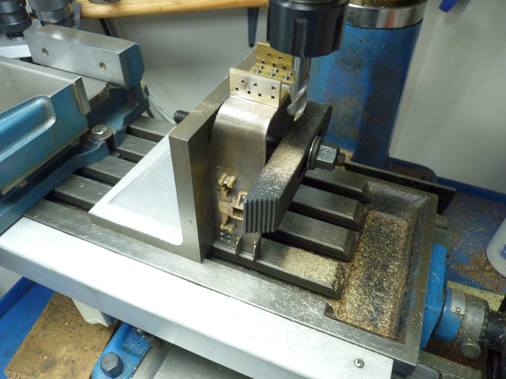
Another couple of hours in the workshop tonight saw the cylinders drilled and tapped for the front covers. Once I was happy that the cover was lined up properly I drilled and tapped one of the holes and then secured the cover with a bolt before proceeding to do the rest of them.
26/10/2020
Well, I went in the workshop tonight with the intention of making a start on the new pistons and rods. I cut two lengths of 4mm stainless bar for the rods and put them in the collet chuck in the lathe to face the ends. I've left them a bit overlength to allow for final fitting to make sure that the pistons will be equal distances from the cylinder end covers at each end of the stroke.
It was then that I found out that I don't have a 5/32" x 40 die for threading the ends of the rods for the pistons!(unless my brother has borrowed it) I've got plenty of the taps. I could have used 4mm x 0.7 instead I suppose but the die that I have for that doesn't look very good quality and it's not a split one so I went on Ebay and ordered a couple of 5/32" x 40 dies (and while I was at it, ordered another 4mm die). So that bit of the job is on hold until one of the dies arrive.
No problem, I'll make the piston blanks instead. I then found that I don't have any suitable gunmetal bar so I've got to order some of that! I intend to fit my usual PTFE rings and no, I didn't have a suitable size of that in stock either. So much for tonights workshop session! I gave up and came back in the house in disgust and did some ordering instead.
To cap it all, I went to boil the kettle and the kettle has packed up! It worked fine an hour before. Definitely one of those days!
28/10/2020
The problem with the kettle turned out to be a dirty contact on the base unit so that's working again. I went around to see my brother today and he had got my 5/32" x 40 die so I 'borrowed' it back and tonight I threaded the ends of the piston rods.
The bronze bar arrived today as well so I machined up the two piston blanks leaving them oversize and roughed out the piston ring groove. I made the pistons the 'LBSC' way where the rod is a plain fit in the hole in the piston for half the thickness and the last half threaded to secure the piston in place.
The rods were held in the collet chuck and the piston blanks screwed on. They were a very tight fit, which you want, and I had to turn them by wrapping some emery cloth around the outside and gripping them with some mole grips. The emery prevented any damage to the pistons and provided a good grip.
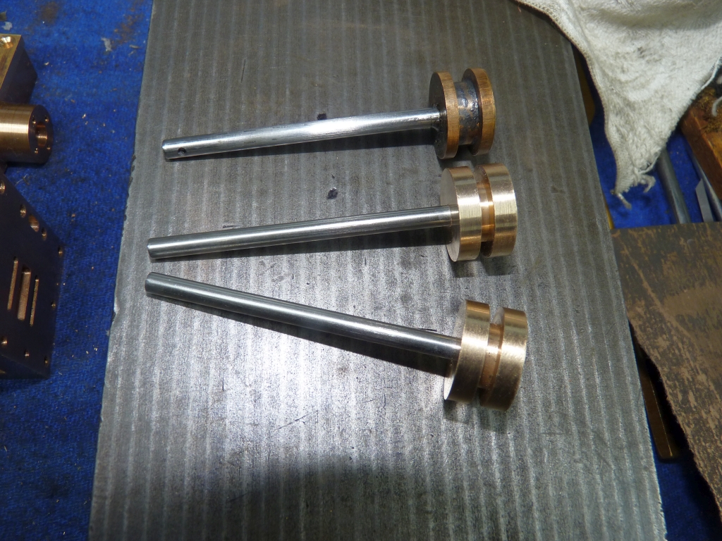
The new pistons on their rods with one of the original ones:
Now it's just a case of holding the rods in the collet chuck and machining the pistons to finished size. I've already done one and turned the outer diameter of the piston to 0.001" less than the diameter of the bore leaving it a nice sliding fit. Both the cylinder and the piston are gunmetal so 1 thou clearance should be adequate. I'll finish the second piston tomorrow hopefully.
27/11/2020
Not much spare time this month so not a lot done in the workshop.
The kettle saga continued. A few days after it first packed up I went to switch it on and there was a flash and a loud bang and the kettle leapt off the base unit! That was it. It went in the bin and I ordered a new one!
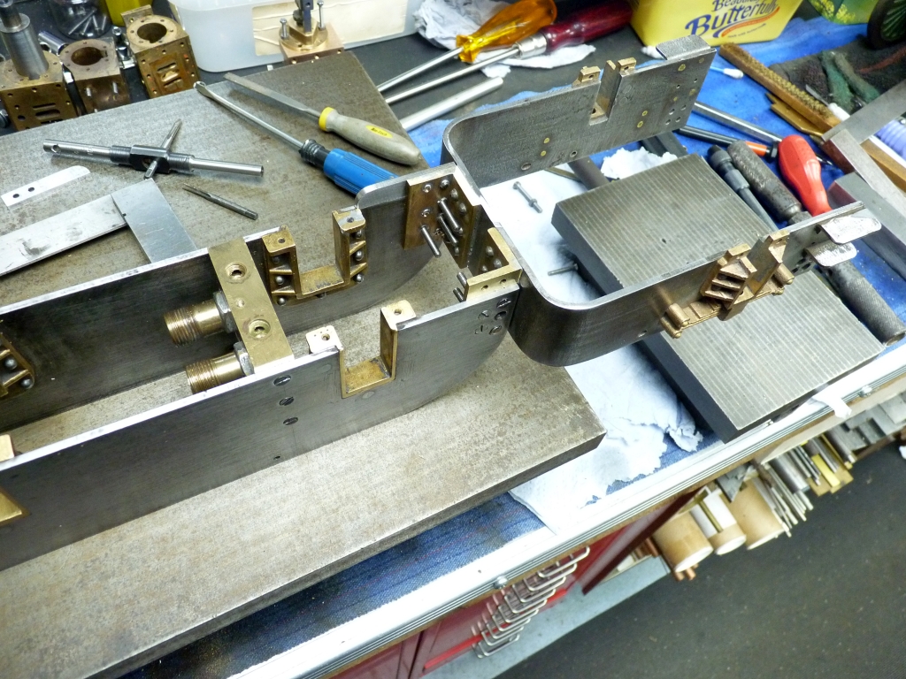
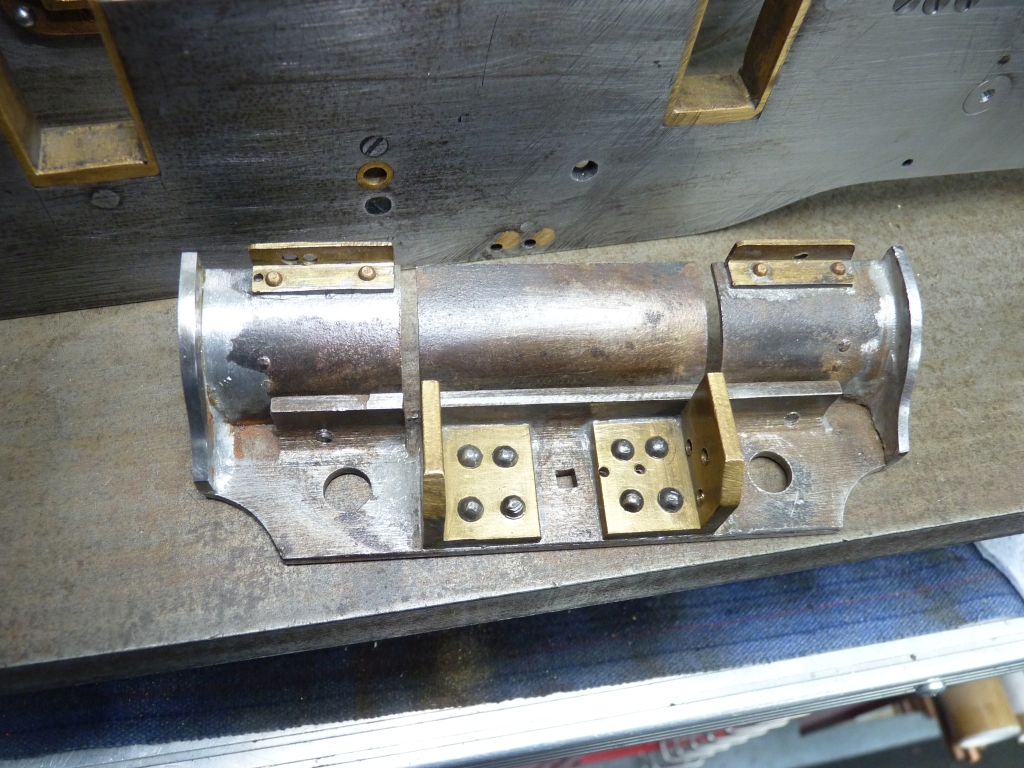
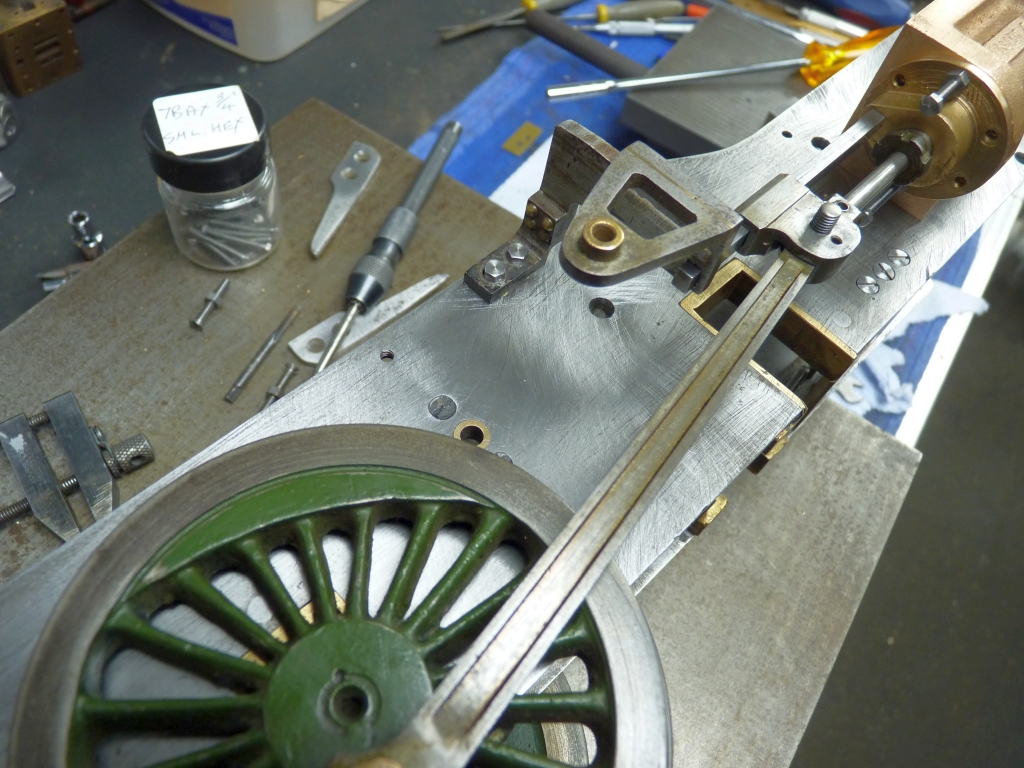
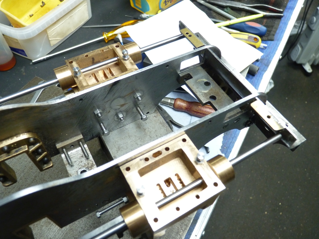
Back to Green Arrow. I decided to see how the motion brackets fitted so bolted the RH cylinder to the frame plate and fitted the motion bracket loosely in place.
Needless to say, it didn't fit very well! The mounting holes more or less lined up but the mounting face of the bracket was not square to the bracket so it pulled it out of line if the fixing bolts were tightened up. I decided to take a skim off the mounting face to true it up. This was done by clamping the bracket in the milling vice with the bottom edge sitting on a parallel and just enough milled off to get the surface flat.
I then tried it in place again and it seemed to need a shim to move it out from the frame plate slightly. I then spent ages faffing about with different shims and adjusting the position of the bracket until the crosshead slid reasonably freely on the slidebar. At this point I wasn't sure how far along the slidebar the crosshead needed to travel so I decided it would now be a good idea to sort out the final length of the piston rod which had been left long to allow for trimming to length.
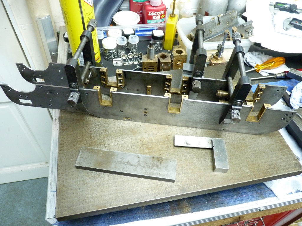
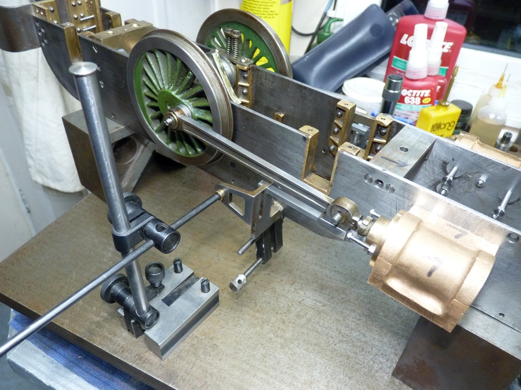
I decided the best way was to temporarily reassemble the frames, fit the centre driving axle and then fit the connecting rods. I could then adjust the length of the piston rods so that there was an equal gap at each end of the cylinder when the piston was at top and bottom dead centres.
I started to bolt the frames back together and realised that they were twisting as soon as the bolts holding the front buffer beam and the rear trailing frame were tightened up. I wasn't surprised as I was sort of expecting this. I checked the slots in the horns across the frames and they weren't in line either! To try and see what was happening, I bolted the frames together using just the axle pump stretcher and the front pony truck stretcher, laid them on the surface plate with one frame plate against the surface plate and then held a square against the ends of the frames. There was a 0.034" gap between the bottom frame plate and the square when the square was touching the top plate. No wonder the frames were out of line.
Looking at the holes for the pump stretcher in the frame plates it was obvious that the frames hadn't been drilled as a pair and the holes were in different positions on the frame plates. The holes for the bogie stretcher were even worse! Fortunately, all the rest of the holes e.g. those for the front buffer beam and the trailing frame seem to line up. It's going to have to be sorted otherwise the axles will be at an angle to the frames and nothing will line up properly. I think I'm going to have to plug the holes in one side of the stretchers and redrill them. That's an easier option than plugging the holes in the frames and redrilling those. More work!
28/11/2020
Tonight I had a look at the pump stretcher and plugged the mounting holes on one side. I drilled them out and retapped them 1/4" x 40 and then screwed in brass plugs held in with Loctite. I chose to use 1/4" x 40 so that the new tapped holes would be entirely within the brass plug and not part in the plug and part in the stretcher.
I then took a skim off the mounting face to bring the plugs flush with the surface and also to make sure that the mounting face was square to the face of the stretcher. I had noticed that the mounting faces were slightly convex which would not help maintain the squareness of the frames. I flipped the stretcher over and took a skim off the other mounting face to make sure that was square and parallel to the first.
Now it's a case of clamping the frames to the stretcher, get them lined up properly, drill and tap the new holes for the mounting bolts and then see what happens when I refit the front buffer beam and the trailing frame.
29/11/2020
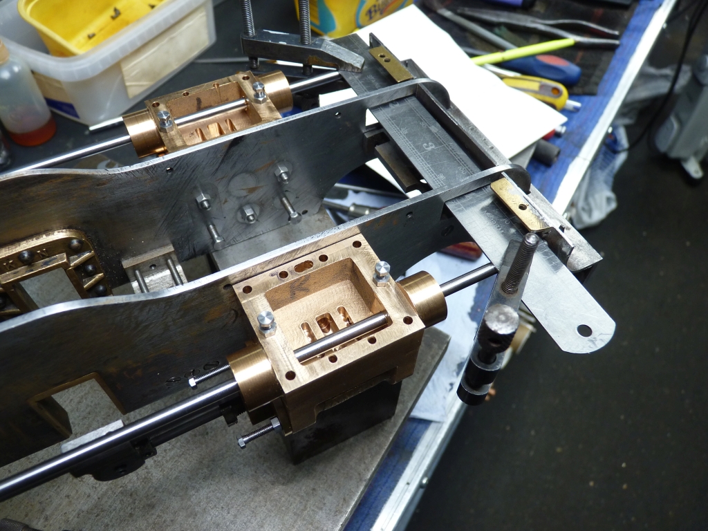
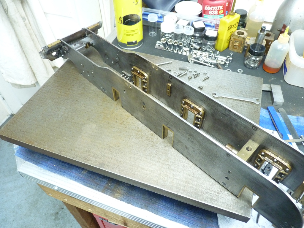
Tonight saw the frames clamped together so that I could spot and drill the new mounting holes in the pump stretcher.
I fastened the pump stretcher and the bogie stretcher to one frame plate and then clamped the other frame plate to them with a couple of machinists clamps. I set the frames on top of one of my surface plates to get the top edge level. Using a square across the ends of the frames I adjusted the position of the 'loose' frame plate until the ends of both plates were level. I also checked the horns to make sure that they were level. The leading and trailing horns were spot on but the middle horns seem to be slightly out. I hope that is not going to cause more problems later on.
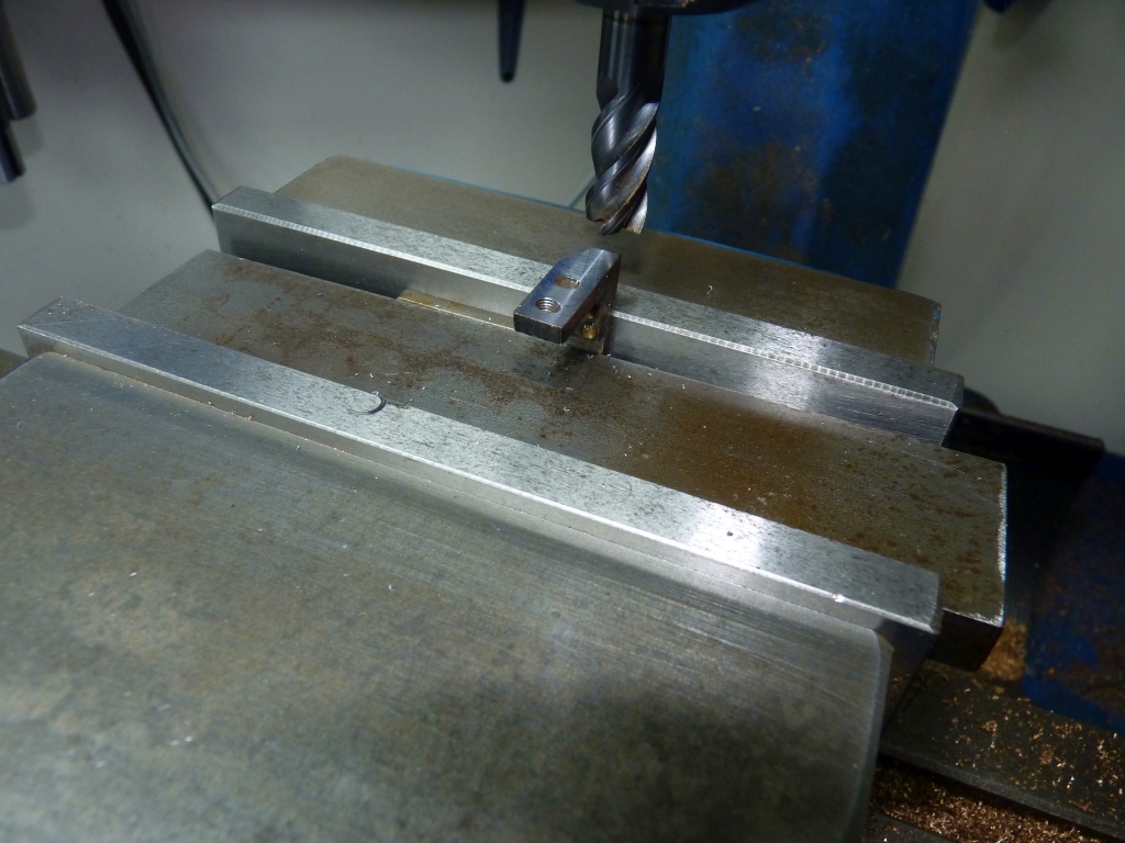
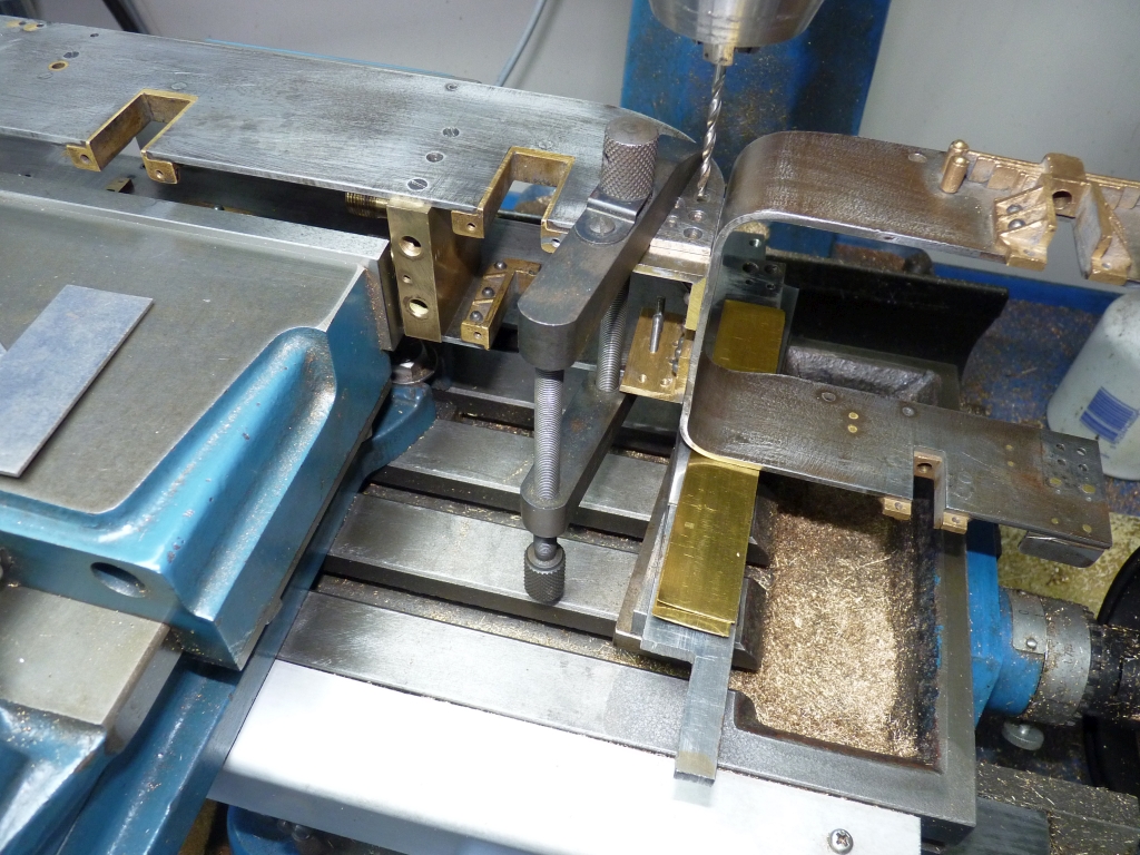
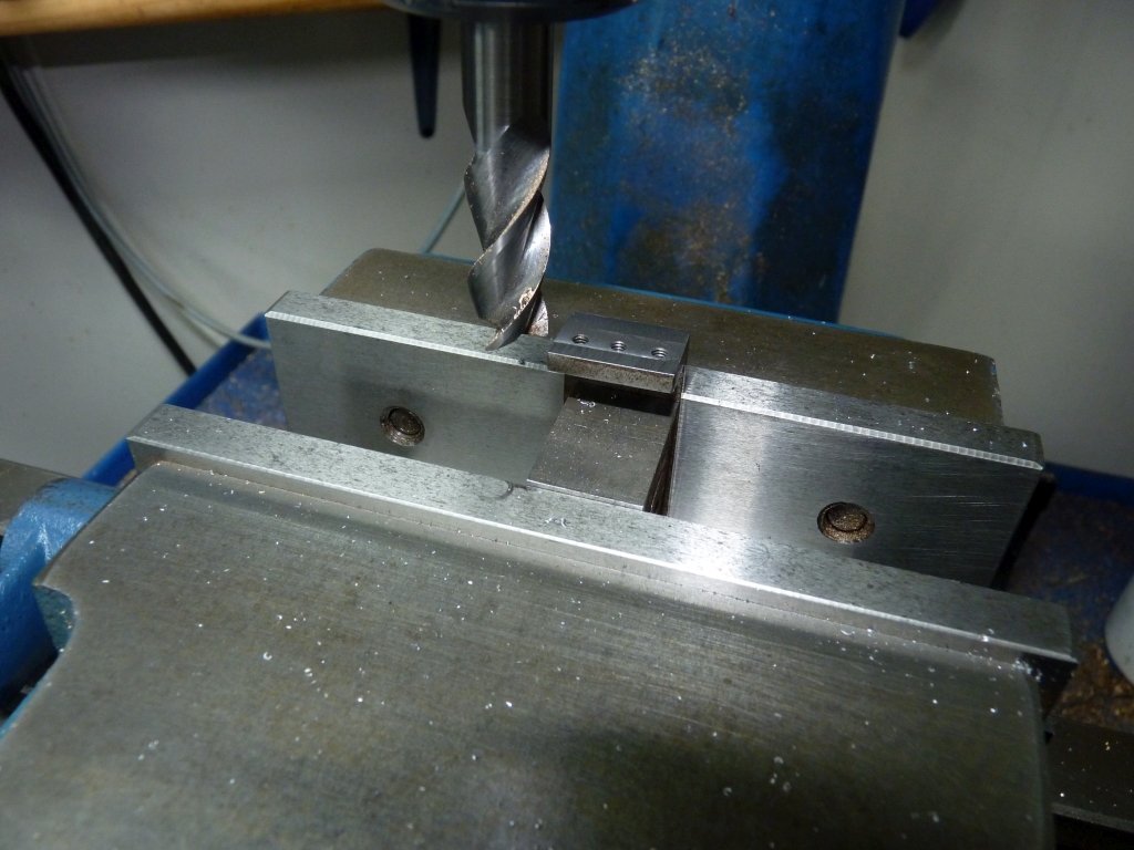
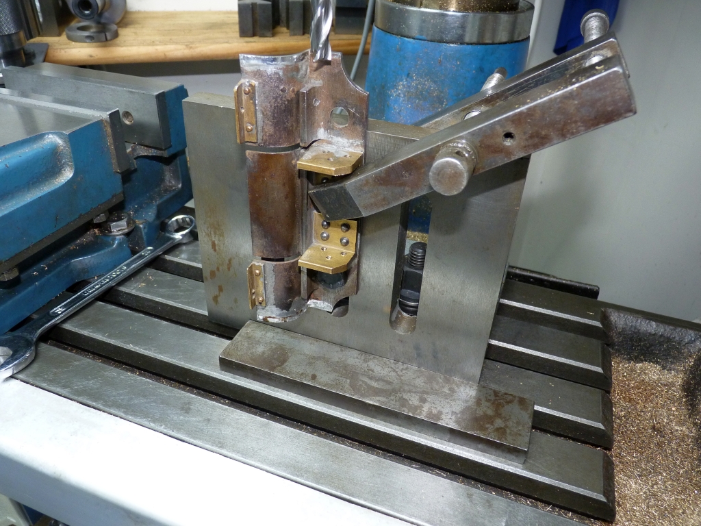
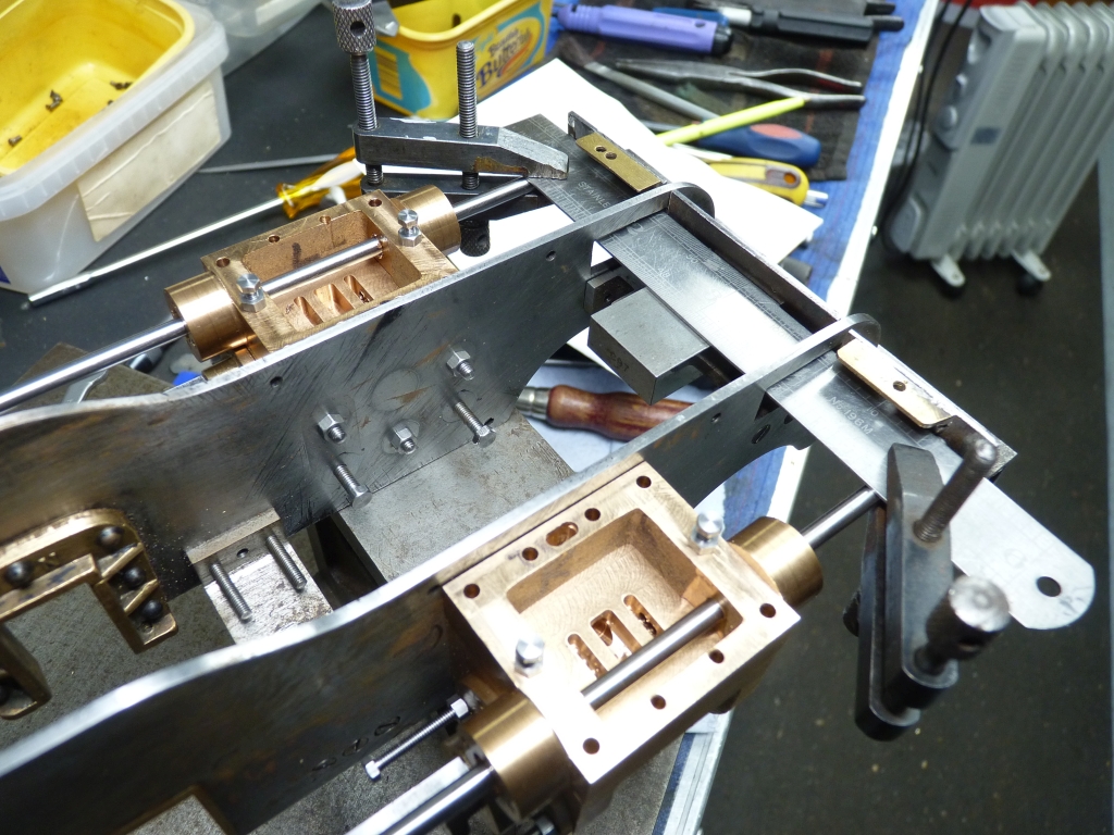
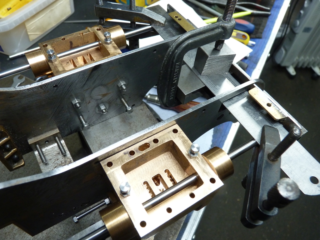
I tightened the clamps and transfered the frames to the mill where I spotted the holes in the frame plate into the pump stretcher. The holes were then drilled and tapped.
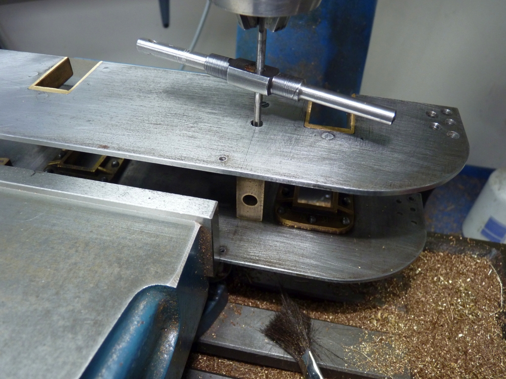
I just did the centre hole first, fitted the screw and then checked the frames on the surface plate again to make sure they were still square which they were. The other two holes were then drilled and tapped. The photo above shows the last hole being tapped. I forgot to take a photo when I was doing the first hole and for that the machinist clamp was still in place to hold the frames secure.
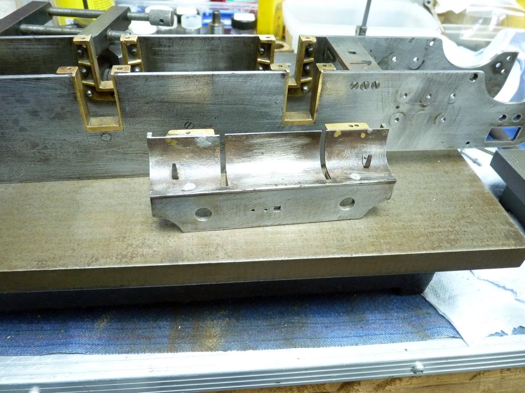
I decided to have a look at the trailing frames next and refit those. When I checked them they were quite a bit out of square and twisted so a bit of bending and tweaking followed to true them up. When I was happy with them I checked the mounting angles and they were not square to the frames (of course!). The width across the outside of the angles was also too big. The width should have been 1.9375" (the width between the mainframes) but it was something like 1.965". The angles therefore needed squaring up and a bit taking of the faces that bolt to the frames.
I had to do a similar job on the trailing frames for the Bonds Pacific chassis that I worked on last year so I did a similar thing to hold these trailing frames in the mill i.e. bolt them vertically to an angle plate.
I had got the frames pretty square earlier so clamped them to the angle plate with the top edge against the angle plate and set the sides vertical with a square which would be accurate enough for this job. I only used one clamp but I only intended to take very light cuts so that would be adequate.
I ended up taking about 0.012" off each of the angles to clean them up.
With hindsight I should have set the angle plate at 90° to how I did as I would have been able to see the faces of both of the angles when I was milling them. As it was I had to do the back face 'blind' although I did use a mirror to see what I was doing!
Before disturbing the set up I checked the distance between the frames at the pump stretcher and it was a bit undersize due to me remachining the stretcher so I decided to take a bit more off the faces of the trailing frame angle to suit. That would save having to put a shim on the pump stretcher to bring the distance between the frames back to nominal. I don't think that 0.010" undersize is going to matter in the general scheme of things.
I tried the trailing frame in the end of the mainframes and they fitted nicely. I put a couple of screws in one side but the holes on the other side don't line up now. They are about 0.030" out!
Once again, I'm going to have to plug the holes and redrill them. You put one thing right and it makes another job! I will probably have a similar problem with the front buffer beam when I come to refit it.
30/11/2020
I'm slowly having a sort out of stuff and trying to get rid of piles of 'junk' that I've collected over the years! Today, I was looking through a box containing two part built 'Sugars', the strange little 2½" gauge loco designed by Rex Tingley. They were donated to the N25GA some years ago and I ended up looking after them. Rummaging through the box I found two lengths of 6BA threaded brass studding which would be ideal for plugging the holes in the mounting flange of the rear trailing truck.
I cut off short lengths and threaded them into the holes in the angle and prepared to soft solder them in. A year or so ago I bought a neat little gas torch from Ebay that gives a nice needle flame and is ideal for jobs like this. Could I find it! I don't know where it's gone and I can't remember where I last used it. I normally keep it on the work bench in the workshop but it wasn't there. I looked in the shed, on the bench under the carport and in the house but it was nowhere to be seen. I haven't lent it to my brother as he's got one of his own.
Rather than dig out the Sievert kit I tried using a hot air gun that happened to be in the workshop and although a bit slow to heat up it worked ok.
The lengths of studding that were proud of the bolting face were filed flush and the trailing frame was ready to be fitted and have the new holes drilled and tapped. That was done in the mill as before.
That went ok and the frames seem to be still square and level.
The next job is to sort the front buffer beam. I have tried fitting that and it has a similar problem as the trailing frame as I expected. The fixing angles are not square or parallel and too wide.
01/12/2020
I decided to tackle the front pony truck stretcher next. With that being a horizontal stretcher it would help maintain the frame alignment whilst I sorted the front buffer beam out. Checking it with a square showed the bolting faces were not parallel or square so it went in the mill to have that sorted out.
Once again, it was too wide but by the time I had trued up the bolting faces the width came out ok.
I put the stretcher back in the frames and to my surprise the bolting holes on both sides lined up almost perfectly. It was obviously the out of square bolting faces that had thrown it out before. That was good news as I didn't have to plug any holes and redrill them this time.
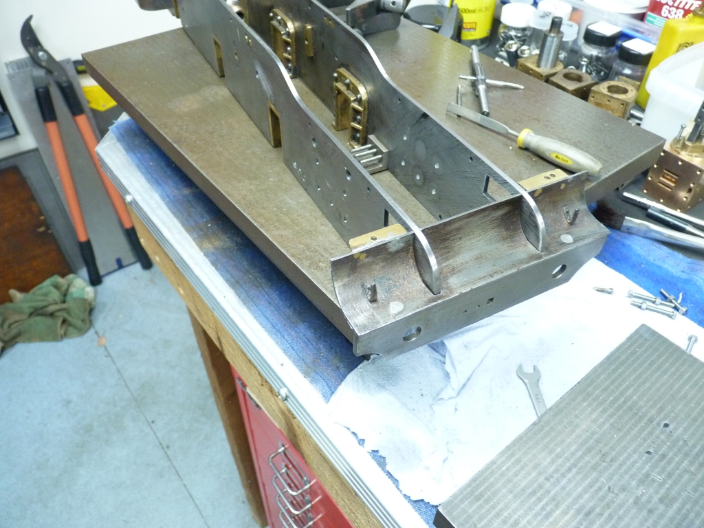
I thought it a good idea to put the wheels back in at this point, fit the coupling rods and make sure that the wheels still went around.
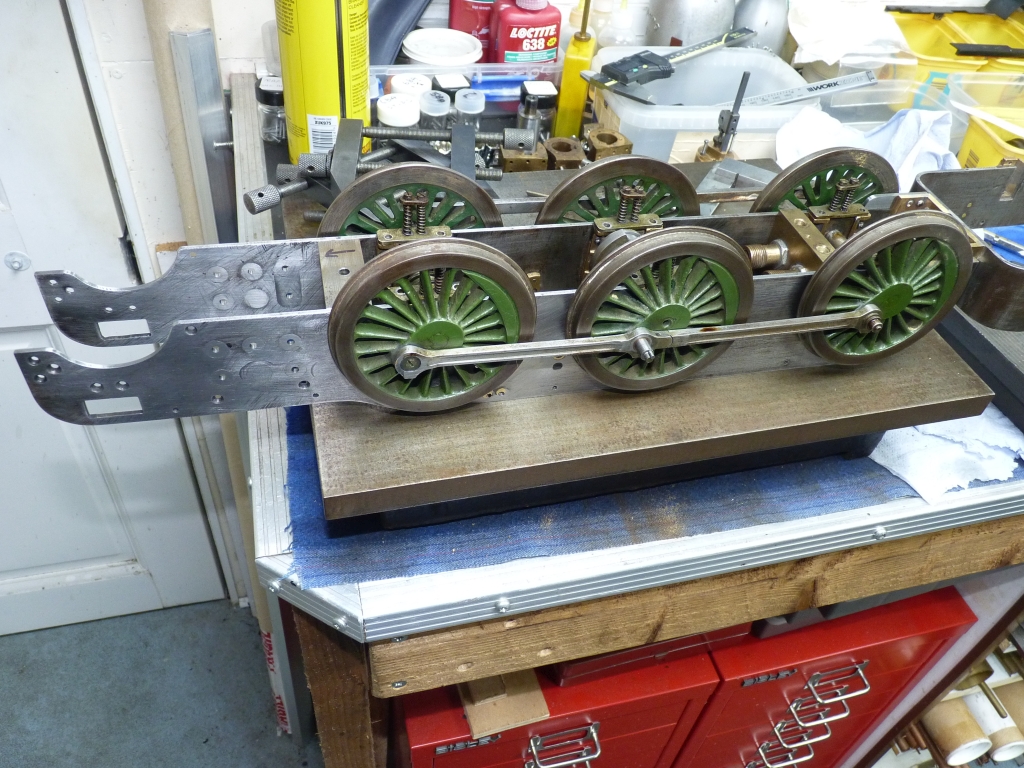
Fortunately, everything seemed ok. There is a slight tight spot at one point of the rotation but that will soon disappear with a bit of running in. In theory, the axles are all in exactly the same place as they were before but hopefully they are now square to the frames instead of at an angle!
I was very pleased with this result and feel as though I have actually achieved something. It's easy to get to the point where you think you are just going round in circles getting nowhere.
Next, on with the front buffer beam. This has the front running boards screwed and soft soldered to it which would make it a bit of a problem to hold in the mill vice.
To remachine the bolting faces of the angles I really needed to mount the buffer beam vertically so that I could get the endmill right into the corner of the angle. That would mean that the valances on the ends of the buffer beam would be in the way but fortunately they are just soft soldered on so easy to remove. I had made a new one of these some time ago as one was missing. It had obviously got knocked off at some time and lost.
I thought about holding it in the milling vice but decided that wouldn't be secure enough and clamped it to an angle plate instead using a bolt and a machinists clamp.
When one face was machined I just flipped it 180° to do the other one. As mentioned earlier, the width across the angles was quite a bit oversize so I milled an equal amount from both faces. I also had to file the slots in the running boards to match the new bolting faces.
A trial fit showed that the buffer beam fitted pretty snugly but I might have to take a bit more off the slots.
The mounting holes are a little bit out on one side and do put a slight twist in the frames when the screws are tightened, causing them to rock on the surface plate. However, the rock is only a couple of thou so I can probably get away with that. It certainly isn't enough to warrant plugging and redrilling again. If the fixing bolts had been ordinary hex headed bolts I could have just elongated the holes in the frame to move them but the fixings are countersink head screws and that's difficult to do as the countersink aligns the screw rather than the hole.
03/12/2020
I've spent the last two evenings trying to sort the front buffer beam and get it so that the frames don't twist when the fixing screws are tightened up. Further investigation showed a twist in one of the frame plates that wasn't helping so that was straightened out. Eventually, I bit the bullet and plugged the holes in one of the fixing angles by tapping them out to 2BA and loctiting some threaded brass plugs in. The holes were then redrilled and tapped with the buffer beam clamped in position and everything seems to be ok now. I can now get back to where I was a week ago!
04/12/2020
Back to trimming the piston rods to the correct length.
I fitted the RH cylinder in place and also the driving axle with the axleboxes set to the running height by putting a spacer (a 5BA nut) between the bottom of the axlebox and the hornstay. The connecting rod was then fitted to the crosshead.
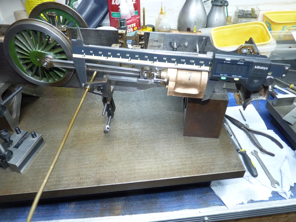
I determined where the front face of the piston should be from the front end of the cylinder when the piston was at mid stroke and then measured the actual distance with the digital calipers. Subtracting one measurement from the other gave me how much needed to come off the piston rod which was 0.158". That seemed a lot but I double checked my dimensions and it seemed correct so I went ahead and removed the excess in the lathe with the piston and rod held in a collet. The piston was held behind the collet so that the end of the piston rod faced towards the tailstock.
I refitted the piston to the cylinder and crosshead and the distance of the piston from the end of the cylinder seemed about right.
The piston didn't hit the rear cover when I rotated the wheel so there is still a gap at that end! Before refitting the piston I checked the piston rod against the old one and the new one was quite a bit shorter. I would guess that the old piston rod was probably too long and only just cleared the front cylinder cover before.
I thought that I would try fitting the motion bracket and it now seems to fit quite well without needing any shims etc.
I'm not happy with the mounting holes in the bracket though. They have been elongated to allow the bolts to fit and are a very sloppy fit on the bolts and I can see the bolts working loose eventually. The original bolts are only 6BA and there are only two of them so I may change them to 5BA and plug and redrill the mounting holes in the bracket to suit.
If I was building a Green Arrow from scratch I think I would redesign the brackets and make a larger bolting flange that could take at least one more bolt to make the assembly more rigid. Also, I don't like the fact that the expansion link is only supported on one side. I could alter the brackets anyway but I don't really want the extra work. The job is taking long enough as it is! I just want to get the loco finished and running.
06/12/2020
Before going any further with the RH motion bracket I decided to trim the LH piston rod as before and then try the LH motion bracket in place to see how that fitted. As with the RH one, I had to remachine the bolting face as it was out of square with the rest of the bracket. When it was temporarily clamped in place it fitted ok but it was obvious that the mounting holes in the frames were way out of line with the holes in the motion bracket. I was going to have to plug the frame and redrill the holes but before doing that I thought it would be a good idea to see if the expansion link trunnion bearing was in the same position on both sides of the frame.
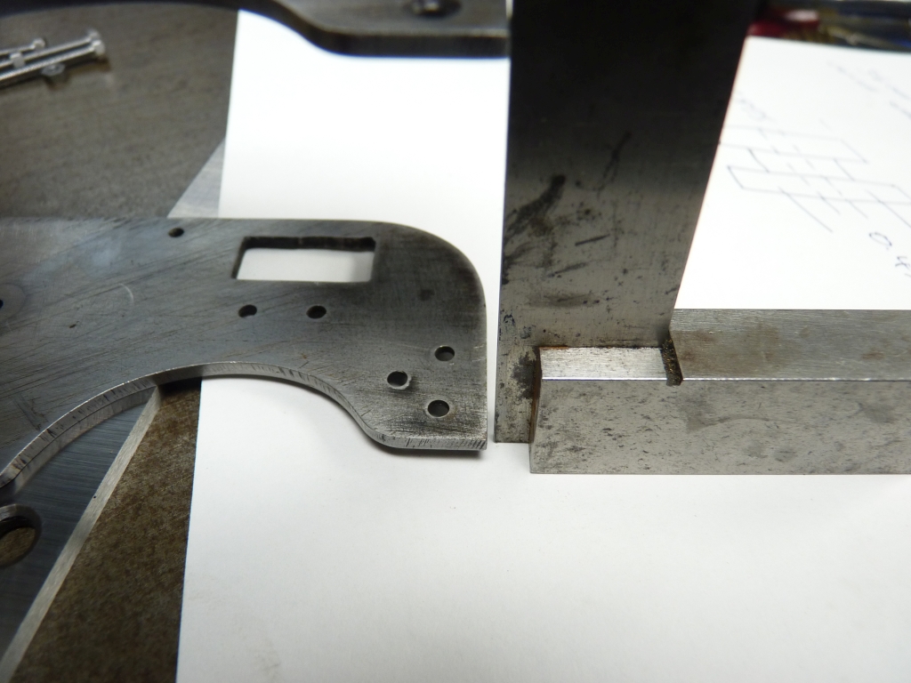
To check the vertical position I put the frame upside down on the surface plate using a couple of vee blocks to act as spacers. I then used the end of the scribe in a surface gauge to locate the bore of the trunnion bearing on one side of the frames and then moved to the other side to see if the height agreed.
The heights were within 0.010" so I was happy with that. There wasn't much I could do to alter the height anyway as the vertical position of the motion brackets is determined by the end of the slidebar.
I thought I had better check the horizontal positions as well. I put a length of 1/8" bar in the bearing and then measured the distance to the front of the cylinder block with a digital caliper. I started with the RH side as I had already determined the position of that motion bracket.
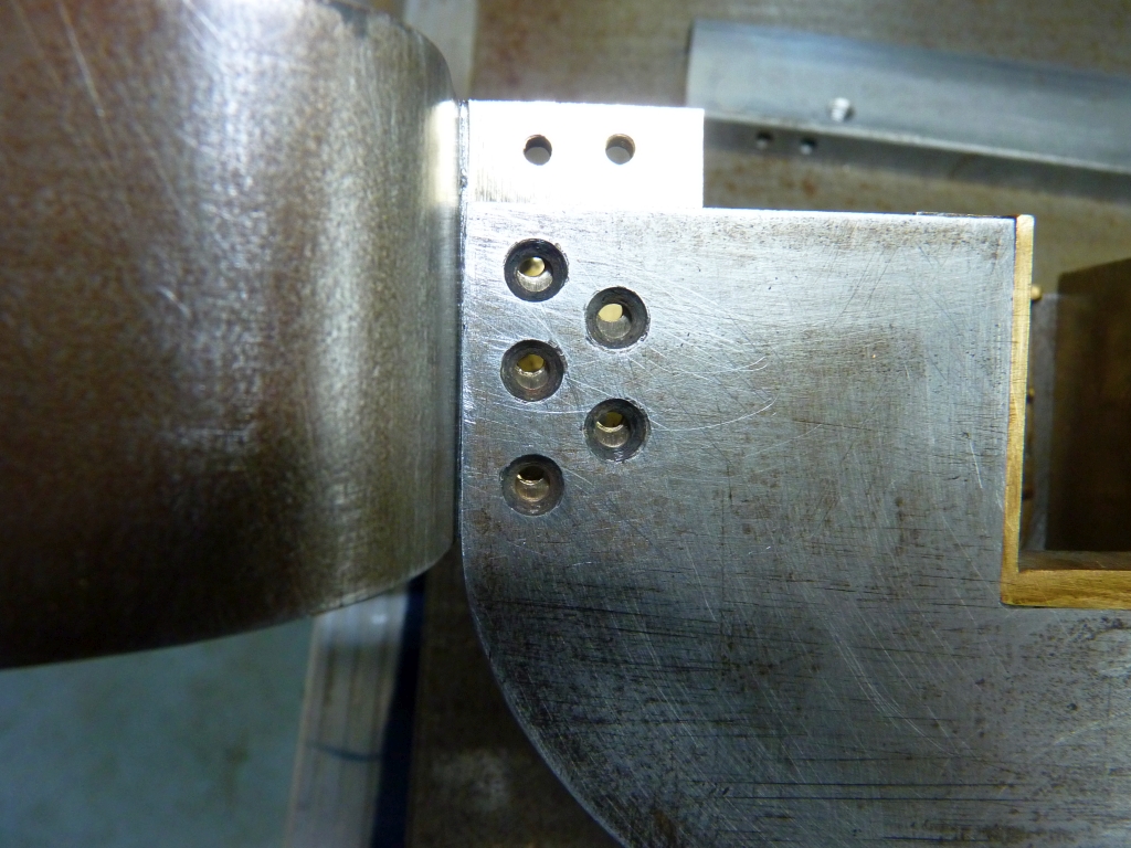
I then did the same on the LH side and there was about 0.030" diference so the LH motion bracket needed to move forwards. As I was going to have to move the holes in the frame anyway that wouldn't be a problem. You can see from the photo below how far out the holes are.
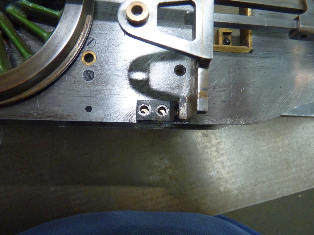
I marked the position of the bracket on the frames using a sharp scriber and then took the cylinders off and removed the driving wheels so that I could plug the old mounting holes in the frames. I just screwed in a couple of short lengths of the 6BA threaded brass rod, soft soldered them in position and then filed the ends down flat.
Next job is to drill and tap the new holes in the frames.
I can't remember whether I have mentioned that I'm looking to build another shed next to the steel one so I can have more storage space for tools and materials. The workshop is overflowing and I am really struggling for space. Before I can make a start on the new shed I've got to get rid of a tree which is in the way. In any case, the tree is too close to the house and the workshop so really needs to be taken down anyway. Over the last couple of years I've severely pruned it but it's too much for me to take it down completely. A chap is coming tomorrow to do it for me so hopefully the new shed build will start soon.
09/12/2020
The tree is now a pile of logs and twigs that need disposing of!
Back to Green Arrow. I decided to plug and redrill the mounting holes in the RH motion bracket as they were very elongated and oversize and would not hold the bracket very securely. Because the holes were elongated I opened them out with a 4mm endmill to get them round again. I then tapped them 2BA and screwed in some steel plugs. This time I silver soldered them in as the enlarged holes would have weakened the bracket so I wanted to regain the strength. Once the plugs had been filed flush the bracket was redrilled 5BA clearance for the new bolts.
This meant that the tapped holes in the frames also needed plugging and redrilling as there was no guarantee that the original holes would now be in the right place. I drilled and tapped them 2BA again and fitted brass plugs soft soldered in place. The motion bracket was clamped in place and new holes drilled and tapped for the 5BA bolts.
I think this motion bracket needs shimming out slightly as the crosshead becomes very tight when the bolts are tightened up. I'm going to leave that until the final assembly though and take a look at the front frame stretcher that carries the pivot for the 2 to 1 lever for the valve gear. That will no doubt be in the wrong place and at the wrong angle!
11/12/2020
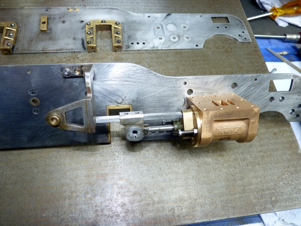
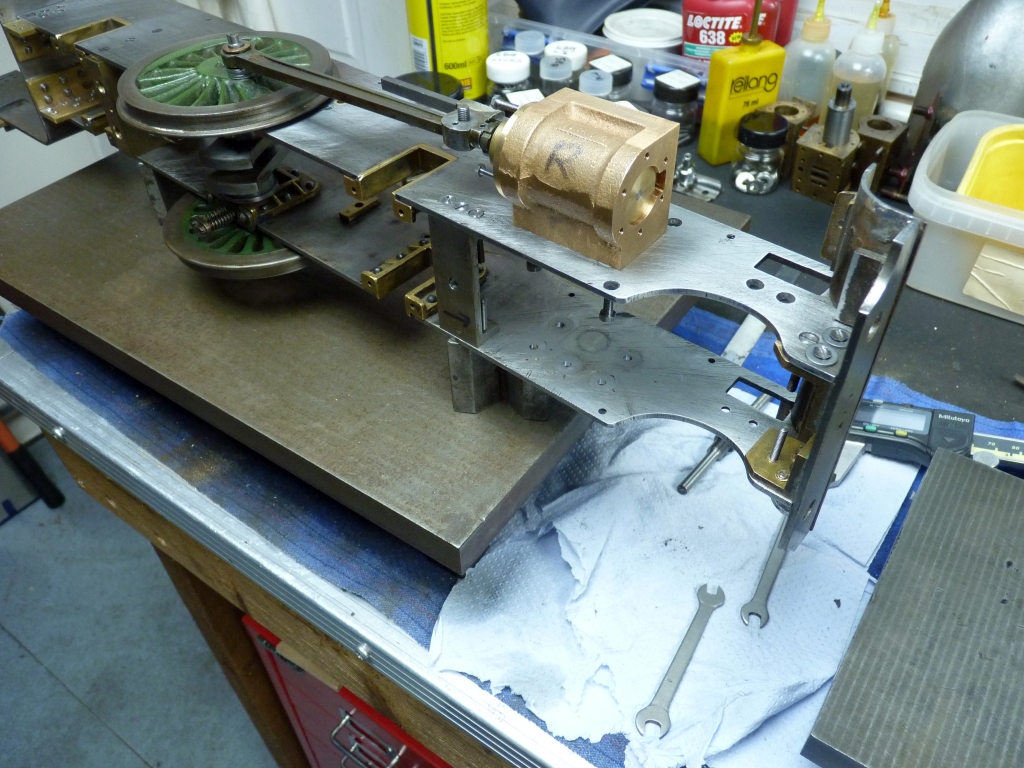
How to get the front frame stretcher in the right place and at the right angle? It has to be at the same angle as the valve rods so I fitted the outside cylinders and the valve chests and put lengths of 4mm silver steel through the valve chests to represent the valve rods. I fitted the stretcher but with only one screw in the RH side so it could be angled to match the rods.
This gave me a datum surface that I could position the stretcher from. Using the 3D model I could measure the distance that the top of the stretcher should be from the top of the valve rods. To make this easier I clamped a 6" steel ruler to the top of the rods. Anything thicker than that wouldn't have gone through the cut outs in the frames for the 2 to 1 levers.
I found that one of my spare gauge blocks fitted nicely in the gap between the top of the stretcher and the ruler. The stretcher is actually too low down in the frames but it can't really be moved higher otherwise it would be higher than the bottom of the frame cut out. I can easily adjust the height of the 2 to 1 levers to compensate for this though so it won't be a problem.
All I had to do now was put a clamp to hold the stretcher to the ruler and it would be at the correct angle to line up with the valve rods.
To my surprise, the second fixing hole on the RH side also lined up perfectly which I wasn't expecting! I think that was pure luck though. I put the other fixing screw in so that the stretcher was now securely held in position and the clamp, block and ruler etc. could be removed out of the way. What didn't surprise me was that neither of the LH fixing holes lined up so they needed to be plugged, redrilled and retapped. I used some short lengths of 6BA bolt to plug the old holes and silver soldered them in as the stretcher is only a small component and easy to heat up to silver soldering temperature.
So, that is the frames sorted out at long last, thank goodness!
I may have to revisit the front stretcher when I get around to fitting the 2 to 1 lever assembly to check that the mounting hole for the lever pivot is in the correct place. It seems to have another hole in it which makes me think that it may have been fitted incorrectly the first time. The stretcher also has a steel plug in it which suggests that someone had a few problems getting the hole in the right place!
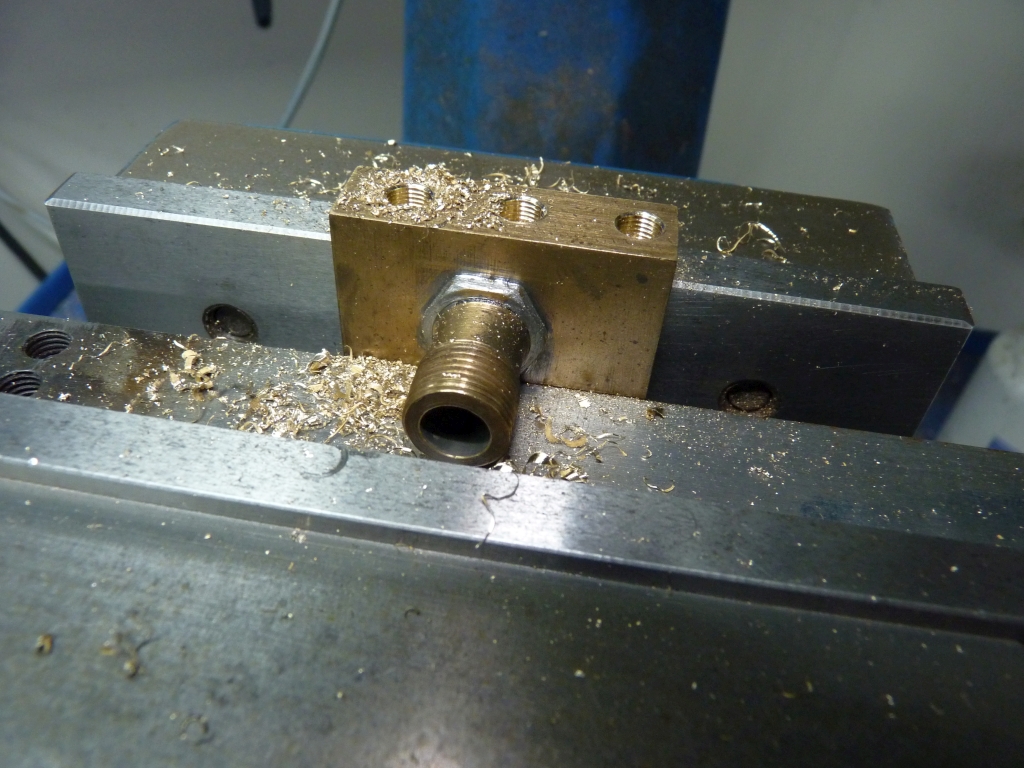
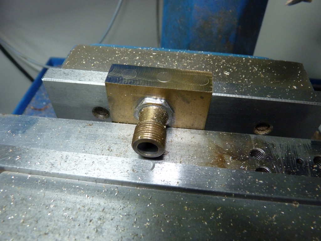
I think now that the frames are done it's time to move on to getting the middle cylinder machined and fitted so that's what we will do next.
To be continued
< Back to Page 3 .....Page 5 >